10.13
Section 10
Reassembly
10
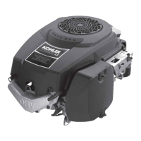
4. With the engine at TDC of the compression
stroke, insert the correct size flat feeler gauge
(see below) between the appropriate valve stem
and rocker arm. Tighten the adjustment nut
with a wrench until a slight drag is felt on the
feeler gauge. Hold the nut in that position and
torque the set screw (T15 Torx drive) to 5.5 N·m
(50 in. lb.). To prevent damage to the nut, torque
the Torx screw only. Perform the adjustment
procedure on the other valve. See Figures 10-44
and 10-45.
Valve Clearance Specifications:
Intake Valve 0.127 mm (0.005 in.)
Exhaust Valve 0.178 mm (0.007 in.)
Figure 10-44. Adjusting Valve Clearance (Lash).
Figure 10-45. Locking Adjustment Nut Set Screw.
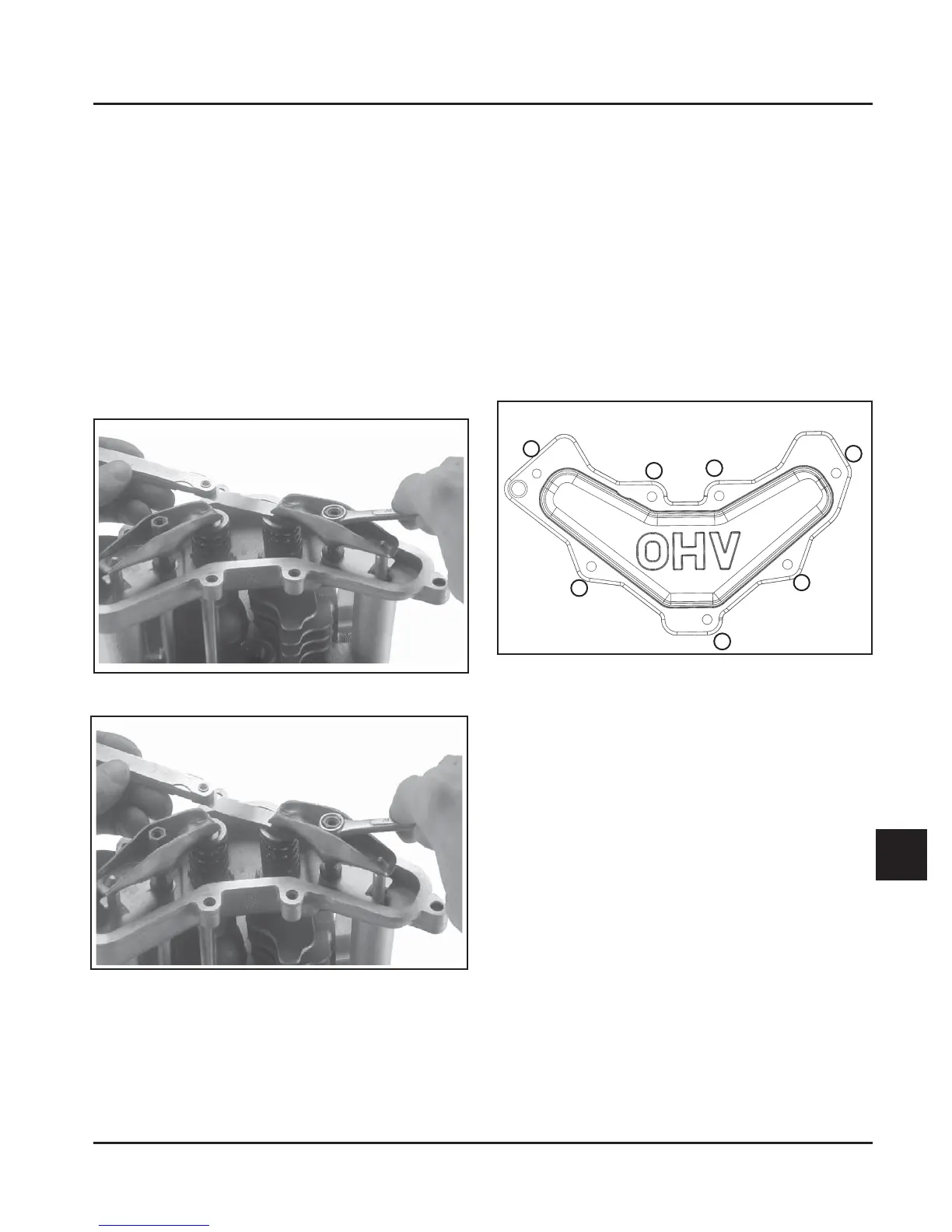
Install Valve Cover
1. Make sure the sealing surfaces of the valve cover
and cylinder head are clean, and free of any nicks
or burrs.
2. Install a new valve cover gasket, followed by the
valve cover. Position any brackets that mount
on the valve cover and start the seven mounting
screws.
3. Torque the valve cover screws to 11.0 N·m
(95 in. lb.) into new, as-cast holes, or 7.5 N·m
(65 in. lb.) into used holes, using the sequence
shown in Figure 10-46.
7
5
2
3
4
1
6
Figure 10-46. Valve Cover Fastener Torque
Sequence.
 Loading...


