5.15
Section 5
Fuel System and Governor
5
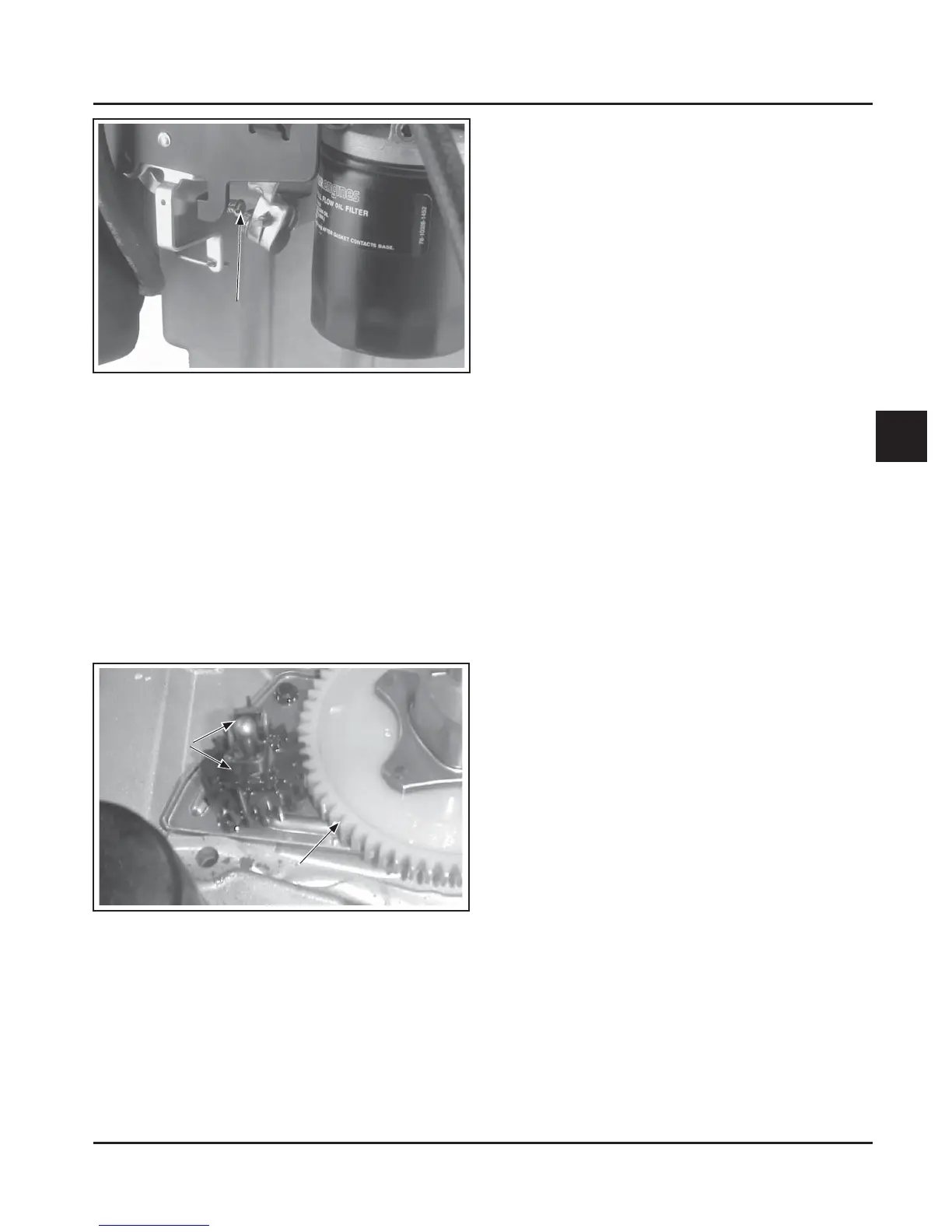
Figure 5-24. Governor Gear/Flyweight Assembly.
Operation
As the governor gear rotates, centrifugal force causes
the flyweights to move outward as speed increases.
As the flyweights move outward, they cause the
regulating pin to move outward.
The regulating pin contacts the tab on the cross sha,
causing the sha to rotate. One end of the cross sha
protrudes through the side of the crankcase.
The governor lever is clamped on the protruding end
of the sha and connected with linkage to the throle
lever on the carburetor, so any rotation of the sha
causes corresponding movement of the throle plate.
When the engine is at rest, and the throle is in the
fast position, the tension of the governor spring holds
the throle plate open. When the engine is operating
(the governor gear assembly is rotating), the force
applied by the regulating pin against the cross sha
tends to close the throle plate. The governor spring
tension and the force applied by the regulating pin are
in equilibrium during operation, holding the engine
speed constant.
When load is applied and the engine speed (and
governor gear speed) decreases, the governor spring
tension moves the governor arm to open the throle
plate wider. This allows more fuel into the engine;
increasing engine speed. This action takes place very
rapidly, so a reduction in speed is hardly noticed. As
the speed reaches the governed seing, the governor
spring tension and the force applied by the regulating
pin will again be in equilibrium. This maintains the
engine speed at a relatively constant level.
The governed speed seing is determined by the
position of the throle control. It can be variable or
constant, depending on the application.
Initial Adjustment
Make this initial adjustment whenever the governor
arm is loosened or removed from the cross sha. To
ensure proper seing, make sure the throle linkage
is connected to the governor arm and the throle lever
on the carburetor. See Figures 5-25 and 5-26.
1. Move the governor lever toward the carburetor
(wide open throle). Do not apply excess force
flexing or distorting the throle link.
2. Grasp the cross sha with pliers, and turn the
sha counterclockwise as far as it will go, then
tighten the hex nut. Torque the hex nut to
7.0-8.5 N·m (60-75 in. lb.).
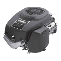
Figure 5-23. Location of Governed Idle Adjusting
Screw.
Governor
These engines are equipped with a centrifugal
flyweight mechanical governor, designed to hold
the engine speed constant under changing load
conditions. The governor gear/flyweight mechanism is
mounted on the closure plate in the crankcase, and is
driven off a gear on the cranksha.
NOTE: Flyweights must be installed perpendicular
to the nylon gear as shown. Improper
installation of the flyweights may cause
damage to the governor gear. See Figure 5-24.
Governed Idle
Adjusting Screw
Flyweights
Nylon Gear
 Loading...


