TP-6694 7/1892 Section 6 Accessories
GM78246E-2
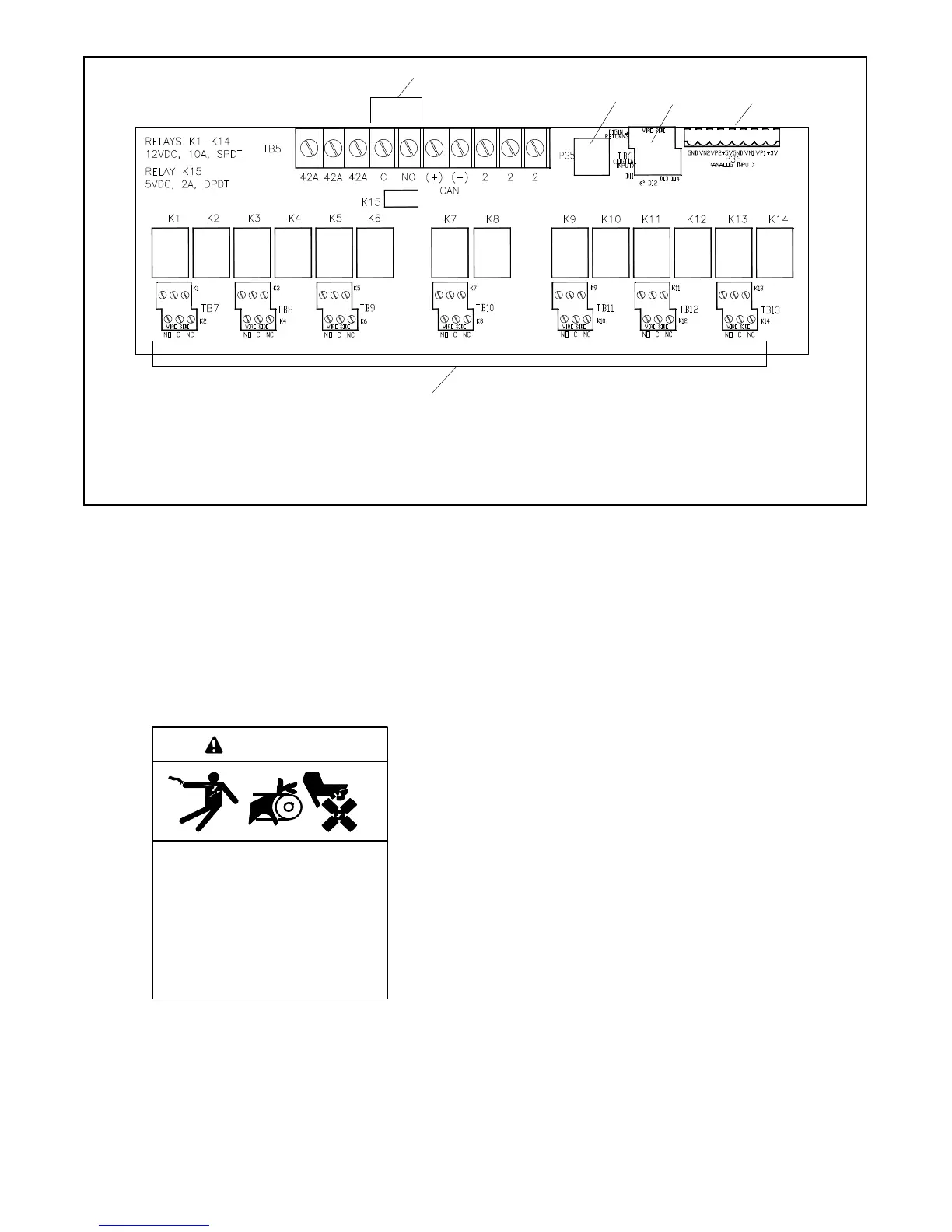
1. TB5 output connections C and NO for the common fault relay K15 (other TB5 terminals are factory connections only)
2. P35 4-position jack connects to controller (factory-connected)
3. TB6 8-position terminal block, digital inputs/digital returns (D11, D12, D13, and D14)
4. P36 8-position pin, analog inputs (see Figure 6-8 for connections)
5. TB7 through TB13, connections for relays K1 through K14 with Normally Open (NO) and Normally Closed (NC) contacts
23 4
5
1
Figure 6-7 15-Relay Dry Contact Board
Connections
For field connections, read the entire Electrical
Connection procedure and perform the steps in the
order shown. Observe applicable local and national
electrical codes when installing the wiring system.
Observe the following safety precautions while making
connections to the kit.
Accidental starting.
Can cause severe injury or death.
Disconnect the battery cables before
working on the generator set.
Remove the negative (--) lead first
when disconnecting the battery.
Reconnect the negative (--) lead last
when reconnecting the battery.
WARNING
Disabling the generator set. Accidental starting can
cause severe injury or death. Before working on the
generator set or equipment connected to the set, disable the
generator set as follows: (1) Press the generator set off/reset
button to shut down the generator set. (2) Disconnect the
power to the battery charger, if equipped. (3) Remove the
battery cables, negative (--) lead first. Reconnect the negative
(--) lead last when reconnecting the battery. Follow these
precautions to prevent the starting of the generator set by the
remote start/stop switch.
Battery short circuits. Explosion can cause severe injury
or death. Short circuits can cause bodily injury and/or
equipment damage. Disconnect the battery before generator
set installation or maintenance. Remove all jewelry before
servicing the equipment. Use tools with insulated handles.
Remove the negative (--) lead first when disconnecting the
battery. Reconnect the negative (--) lead last when
reconnecting the battery. Never connect the negative (--)
battery cable to the positive (+) connection terminal of the
starter solenoid. Do not test the battery condition by shorting
the terminals together.
Leads 42A and 2 provide power to the relays. Do not
use terminals 42A (+) or 2 (GND) on the controller
connection kit terminal strip to supply voltage to
user-supplied accessories. User-supplied DC
 Loading...

