Ethernet/IP Communications | 6 Communication Profile
6.1.3 Data Types
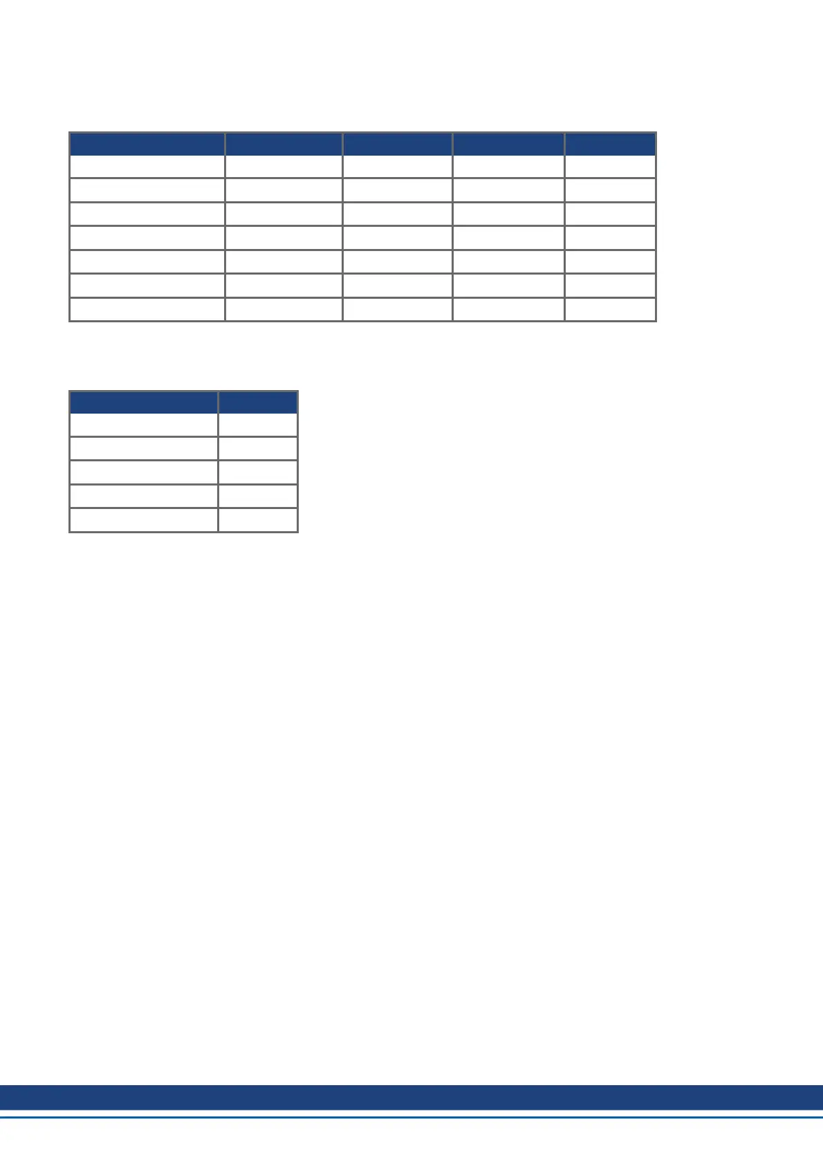
The table below describes the data type, number of bytes, minimum and maximum Range.
Data Type Number of Bytes Minimum Value Maximum Value Abbreviation
Boolean 1 0(false) 1(true) Bool
Short Integer 1 -16 15.875 S8
Unsigned Short Integer 1 0 31.875 U8
Integer 2 -4096 4095.875 S16
Unsigned Integer 2 0 8191.875 U16
Double Integer 4 -2
28
2
28
-1 S32
Unsigned Double Integer 4 0 2
28
-1 U32
6.1.4 Error Codes
The following error codes may be returned in response to an Explicit Message.
Error Error Code
Not Settable 0x0E
Attribute Not Supported 0x14
Service Not Supported 0x08
Class Not Supported 0x16
Value is Out of Range 0x09
6.2 I/O Assembly Messaging (cyclic)
The cyclic data exchange includes the transmission and reception of data values like set point values (e.g.
Position set point, velocity set point or control word) and actual values (actual position value, actual velocity
or status word) between the master and the drive.
The data commands and responses contain multiple values in pre-defined data structures, called assemblies.
AKD defines one Command Assembly (sent from the controller to the drive) and one Response Assembly
(sent from the drive to the controller).
Assemblies are transmitted on a timer according to the Expected Packet Rate.
I/O Assembly Messages and Explicit Messages may be used simultaneously.
6.2.1 Controller Configuration
A controller must be configured with the correct assembly information in order to open an IO connection to the
AKD. This setup will differ depending on the controller type.
See the guide Using AKD with EtherNet/IP and RSLogix for information specific to Allen Bradley controllers.
In addition to configuring the IP address of the AKD in the controller setup, the following values must be con-
figured:
Input Assembly (also called Response Assembly or “Target to Originator Connection”)
Instance: 102
Size: 64 bytes
Run/Idle Header: No
Output Assembly (also called Command Assembly or “Originator to Target Connection”)
Instance: 101
Size: 64 bytes
10 Kollmorgen | December 2014

 Loading...


