Enable State: This bit reflects the enable state of the amplifier.
Homed: This bit is set when the drive has been successfully homed.
Current Direction: This bit reflects the actual direction of motion.
General Fault: This bit indicates whether or not a fault has occurred.
In Position: This bit indicates whether or not the motor is on the last targeted position
(1=On Target).
Block in Execution: When set, indicates the amplifier is running a motion task.
Executing Block # (Byte 1 in Response Assembly): Indicates the index of the currently executing Motion
Task when the Block in Execution bit is set.
In Motion: This bit indicates whether a trajectory is in progress (1) or has completed (0).
This bit is set immediately when motion begins and remains set for the entire motion.
6.2.3.3 Status Word 2
Byte Bit 7 Bit 6 Bit 5 Bit 4 Bit 3 Bit 2 Bit 1 Bit 0
2 Load Com-
plete
Reserved Reserved Neg SW
Limit
Pos SW
Limit
Neg HW
Limit
Pos HW
Limit
Reserved
Load Complete: This bit indicates that the command data contained in the command message has been
successfully loaded into the device. Used for handshaking between
the controller and amplifier – see Data Handshaking.
Negative SW Limit: This bit indicates when the position is less than or equal to the Negative Software Limit
Position.
Positive SW Limit: This bit indicates when the position is greater than or equal to the Positive Software
Limit Position.
Negative HW Limit: This bit indicates the state of the Negative Hardware Limit Input.
Positive HW Limit: This bit indicates the state of the Positive Hardware Limit Input.
6.2.3.4 Response Type 0x05 - Actual Torque
This I/O response assembly is used to return the actual torque (current) of the motor in milliarms. Data will be
received in the Data field, bits 4-7. Set Response Type = 0x05 in the command assembly to read this value.
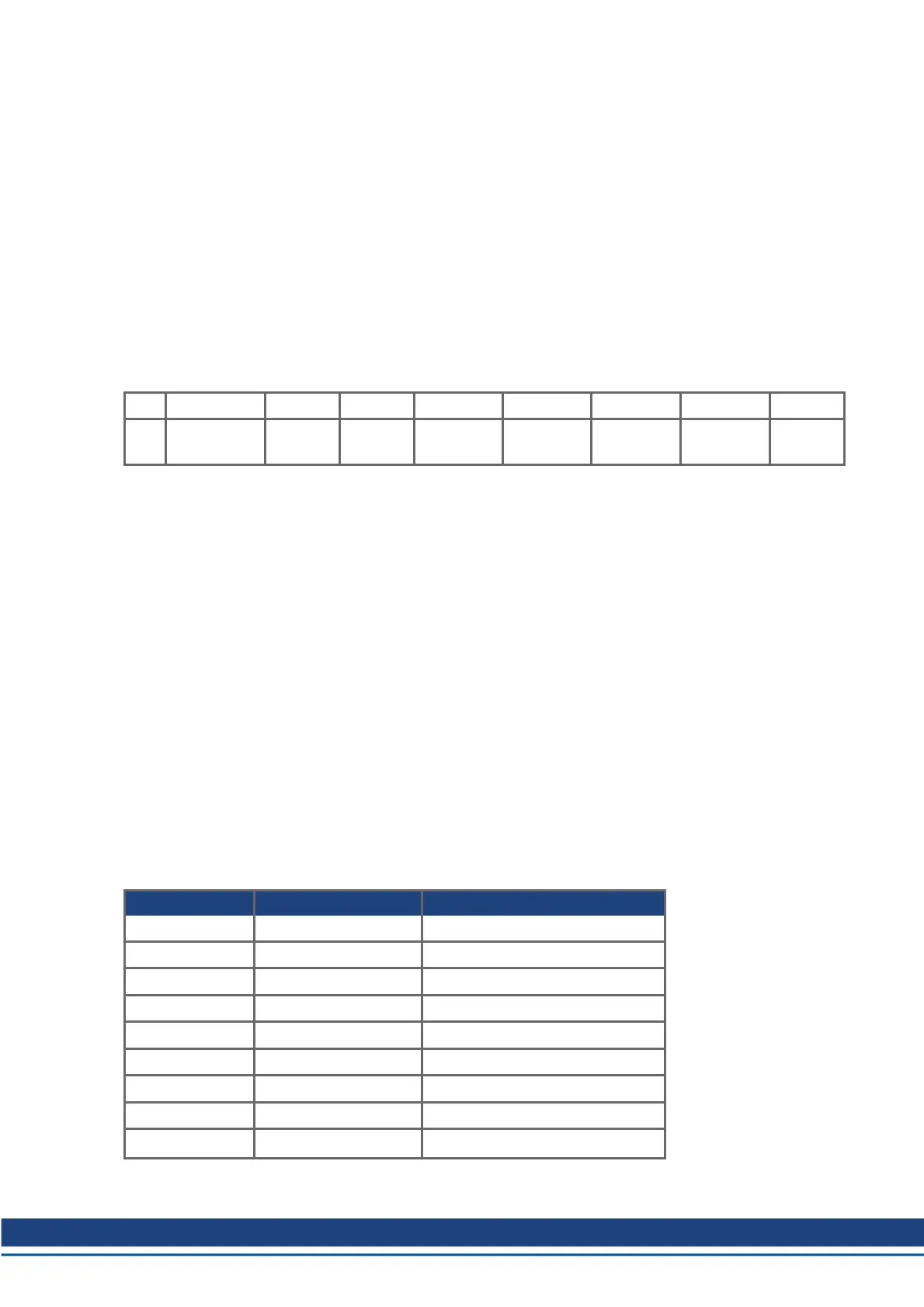
6.2.3.5 Response Type 0x14 - Command/Response Error
This I/O response identifies an error that has occurred. This response will always be returned in response to
an invalid Command Assembly. The Response Type field of the response assembly usually echoes the
matching field from the previous command assembly. But in the case of an invalid command assembly, the
Response Assembly Type field of the response assembly will be set to 0x14 and error codes will be returned
in the Data field.
Error Code (hex) Additional Code (hex) EtherNet IP Error
0 FF NO ERROR
2 FF RESOURCE_UNAVAILABLE
5 FF PATH_UNKNOWN
5 1 COMMAND_AXIS_INVALID
5 2 RESPONSE_AXIS_INVALID
8 FF SERVICE_NOT_SUPP
8 1 COMMAND_NOT_SUPPORTED
8 2 RESPONSE_NOT_SUPPORTED
9 FF INVALID_ATTRIBUTE_VALUE
Ethernet/IP Communications | 6 Communication Profile
Kollmorgen | December 2014 15

 Loading...


