Operation - Section 32 OM3223
Page 32-14 Operator Cab and Controls
Engine Cold Weather Start-
ing Aid (Optional)
Engine starting aid switch (8) is
spring-loaded to the OFF posi-
tion. Use only when the ambi-
ent temperature is below 10° C
(50° F). When the switch is
held in the ON position, ether is injected into the
engine intake manifold to aid engine starting in cold
weather. Move the engine starting aid switch to the
ON position while cranking engine, for three seconds
maximum, and then release engine starting aid. If the
engine does not start, wait at least fifteen seconds
before repeating the procedure. Refer to Operating
Instructions, for more specific operating details.
Rotating Beacon Light Switch
(Optional)
If the truck is equipped with the
optional rotating beacon light (9),
it will be activated by this rocker-
type switch when it is pressed
toward the ON position.
Heated Mirror Switch
(Optional)
If the truck is equipped with the
optional heated mirror (10), it will
be activated by this rocker-type
switch when it is pressed toward
the ON position.
Leakage Test Switch (Trolley Option Only)
Leakage current test switch (11) provides a means
for testing the current leakage relay circuitry of the
trolley system. This circuitry is designed to react to
short circuits between the trolley assist propulsion
system and the truck chassis.
This test must be performed before operating the
truck. Starting with the master control switch in the
DIESEL position, this leakage current test switch
must be held in the ON position for four seconds. If
the system is operating correctly, the trolley fault indi-
cator lamp (D7, Figure 3-7) will turn on. If the light
does not turn on, notify maintenance personnel. The
truck can still be operated in the diesel mode.
To reset, after the trolley fault indicator lamp turns on,
move the master control switch to the trolley position
for a minimum of one second, and then back to the
DIESEL position.
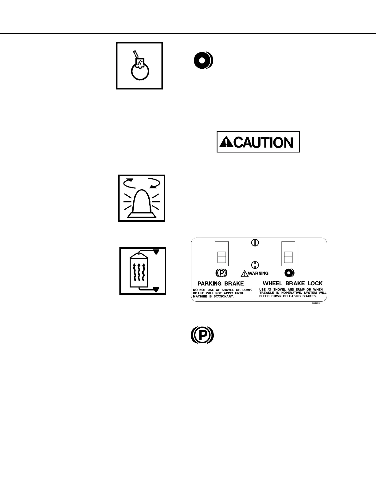
Wheel Brake Lock Control
Wheel brake lock (12) is to be used with
the engine on for dumping and loading
operations only. The brake lock switch
actuates the hydraulic brake system
which locks the rear wheel service brakes only.
When pulling into the shovel or dump area, stop the
truck using the foot-operated service brake pedal.
When the truck is completely stopped and in loading
position, apply the brake lock by pressing the rocker
switch toward the on symbol. To release, press the
rocker switch toward the off symbol.
Use at the shovel and dump only to hold the
truck in position.
Do not use this switch to stop the truck, unless
the service brake pedal is inoperative. Use of this
switch applies rear service brakes at full, unmod-
ulated pressure!
Do not use the brake lock for parking. With the
engine stopped, hydraulic pressure will bleed
down, allowing the brakes to release!
Parking Brake Control
The parking brake (13) is spring applied
and hydraulically released. It is designed
to hold a stationary truck when the
engine is turned off and key switch is
turned OFF. The truck must be completely stopped
before applying the parking brake, or damage may
occur to the parking brake. To apply the parking
brake, press the rocker switch toward the on symbol.
To release the parking brake, move parking brake
control (13) toward the off symbol. When the key
switch is ON and the parking brake switch is applied,
the parking brake indicator light (A3, Overhead
Panel) will be illuminated.
NOTE: Do not use the parking brake at the shovel or
dump. With the key switch ON and the engine on,
sudden shock caused by loading or dumping could
cause the system's motion sensor to release the park
brake.