38
Screws
Thrust washers
Foot switch
Foot switch
connector
Spacers
Bracket
The band
which is
binding wires
BB BB
R
R
R
R
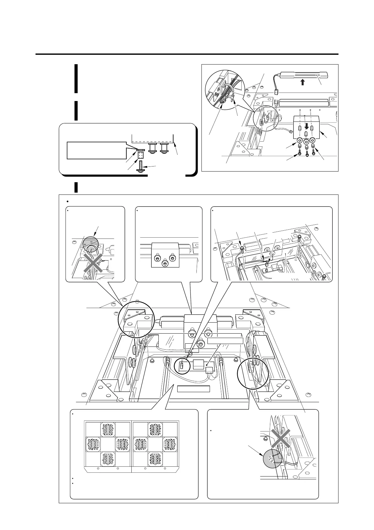
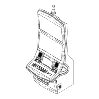
Pay attention to the following points when mounting the foot switch.
When setting the foot
plate, pay attention not to
pinch the wires.
It is normal that the bracket
can be moved even when the
screws is tightened firmly.
Connect the connector through the opening of the
transparent cover.
Opening
Connector
Screws
Transparent cover
Lamp unit
Pay attention to the foot panel setting direction.
Arrange the lamp units in the same direction as shown.
Pay attention to the lamp unit setting position which
differs depending on its color.
"R (Red)" or "B (Blue)" is printed on the inverter PCB.
Pay attention not to
pinch or tread the
wires when setting
the lamp unit.
Inverter PCB
7 Maintenance
MEMO
•Do not mount the thrust washers in
wrong direction.
Screws
Thrust washers
Spacers
Bracket
Direct the Teflon-coated
part of the thrust washer
to the bracket side.
5 Cut off the band which is binding
wires and pull out one foot switch
connector.
6 Remove the bracket which holds
the foot switch.
7 Mount the foot switch in the reverse of dismounting.