104
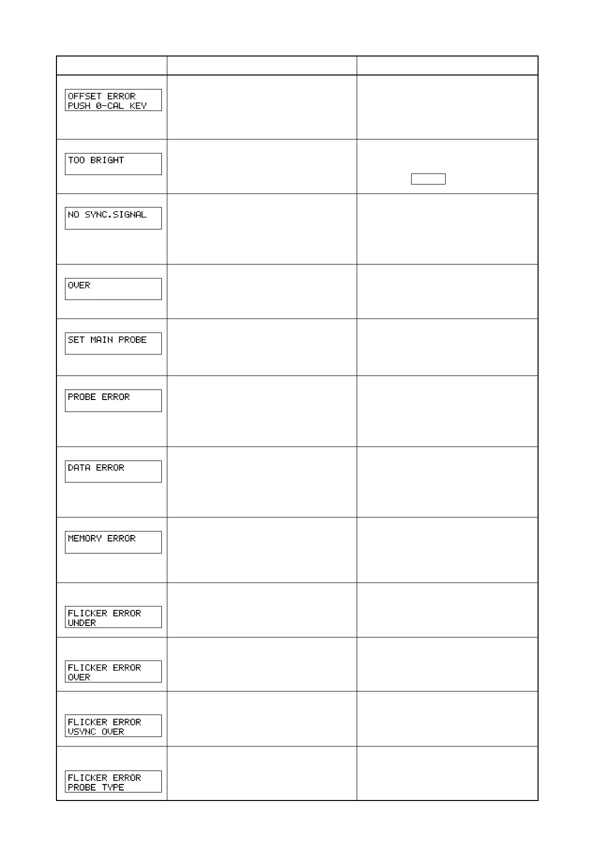
OFFSETERROR
TOOBRIGHT
NOSYNC.SIGNAL
OVER
SETMAINPROBE
PROBEERROR
DATAERROR
MEMORYERROR
FLICKERERROR
UNDER
FLICKERERROR
OVER
FLICKERERROR
VSYNCOVER
FLICKERERROR
PROBETYPE
Error Message
Cause: (Description) Corrective Action
• Zero calibration has not been performed
correctly.
(Zero calibration was performed with insuf-
ficient blocking of entry of light.)
• Pressure is given to purobe.
• Perform zero calibration again. (Page 34)
(
Even if the error message is currently displayed,
measurement will start if the measuring probe’s re-
ceptor is exposed to light.
)
• Don
’
t give the pressure.
• Zero calibration is being performed with
insufficient blocking of entry of light.
• Block the light completely for all the
measuring probes, and when “DARKEN
PROBE PUSH 0–CAL KEY” appears
press the 0–CAL key again. (Page 34)
•
Although EXT SYNC mode is selected, the verti-
cal synchronizing signal used for the display is not
input correctly to the terminal on the instrument.
•
The vertical synchronizing signal used for the dis-
play is outside the range of 40 to 200 Hz.
•
Input the vertical synchronizing signal correctly.
(When the vertical synchronizing signal is out-
side the range of 40 to 200 Hz/page 28)
• Change SYNC mode to NTSC, PAL, UNIV or
INT mode and start measurement.
• The measured value is exceeding the
instrument’s measurement range.
• The measured value is above 100,000% in
analyzer mode. (Display range over)
• Measurement must be performed within
the measuring range.
• The measuring probe is not connected to the
probe connector [P1] properly.
• Connect the probe to the probe connec-
tor [P1] properly.
(Before connecting/disconnecting the
measuring probe, make sure that the
POWER switch is set to OFF.)
• A measuring probe was connected or dis-
connected while the POWER switch was
ON.
• Set the POWER switch to OFF first, con-
nect the measuring probe, then set the
POWER switch to ON.
(Before connecting/disconnecting the
measuring probe, make sure that the
POWER switch is set to OFF.)
• Measurement is not possible since the mea-
suring circuit is not functioning correctly.
• Set the POWER switch to OFF.
If this error still appears even if the
POWER switch is set to ON, the instru-
ment has broken down.
Contact a Konica Minolta authorized ser-
vice facility.
• The instrument’s memory is abnormal.
• If the message disappears when the probe
is changed, the probe's memory is abnormal.
•
If the message keeps appearing when the probe is
changed, the main body's memory is abnormal.
• Set the POWER switch to OFF.
If this error still appears even if the
POWER switch is set to ON, the instru-
ment has broken down.
Contact a Konica Minolta authorized ser-
vice facility.
• Lv is below the instrument’s flicker mea-
suring range.
• Measurement must be performed within
the measuring range.
• Flicker value
(contrast method) has ex-
ceeded 100.0%.
• Measurement must be performed within
the measuring range.
• VSYNC is exceeding 130 Hz in flicker
mode.
• In the case of flicker mode, VSYNC of
40 to 130 Hz must be input.
*3
*4
*3
*4
*3
*5
*3
*4
• A measured probe not for LCD flicker mea-
suring is selected in Flicker Mode.
• In Flicker Mode, select a measured probe
for LCD flicker measuring.
Contact a Konica Minolta
-
authorized
service facility.
Contact a Konica Minolta
-
authorized
service facility.