Figures
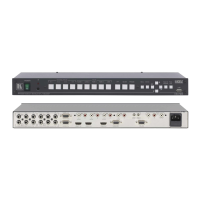
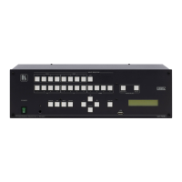
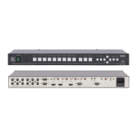
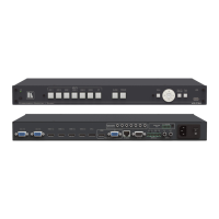
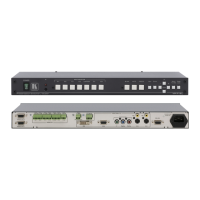
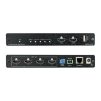
Figure 1: VP-728 Presentation Switcher / Scaler Front Panel 7
Figure 2: VP-728 Presentation Switcher / Scaler Rear Panel 7
Figure 3: Connecting the VP-728 Rear Panel 12
Figure 4: Connecting to a PC via RS-232 13
Figure 5: PIP Source Over Background 15
Figure 6: OSD SWAP Status 16
Figure 7: Infrared Remote Control Transmitter 19
Figure 8: MENU Items 20
Figure 9: Input Screen 21
Figure 10: Picture Screen 23
Figure 11: Output Screen 24
Figure 12: PIP Screen 25
Figure 13: Audio Screen 26
Figure 14: Geometry Screen 27
Figure 15: Setup Screen 28
Figure 16: Advanced Setup Screen 30
Figure 17: Misc Setup Screen 31
Figure 18: Information Screen 34
Figure 19: TextOverlay Application Screen 35
Figure 20: RS-232 PINOUT Connection 37
Figure 21: Splash Screen 38
Figure 22: Atmel – Flip Window 39
Figure 23: Device Selection Window 39
Figure 24: Selecting the Device Window 40
Figure 25: Loading the Hex 40
Figure 26: RS-232 Window 41
Figure 27: Atmel – Flip Window (Connected) 41
Figure 28: Atmel – Flip Window (Operation Completed) 42
Tables
Table 1: Front Panel Presentation Switcher / Scaler Features 8
Table 2: Rear Panel Presentation Switcher / Scaler Features 9
Table 3: PIP Source Appearance Availability 17
Table 4: Infrared Remote Control Transmitter Functions 19
Table 5: Input Screen Functions 21
Table 6: Picture Screen Functions 23
Table 7: Output Screen Functions 24
Table 8: PIP Screen Functions 25
Table 9: Audio Screen Functions 26
Table 10: Geometry Screen Functions 27
Table 11: Available Settings for Each Application 27
Table 12: Setup Screen Functions 28
Table 13: Mode Set Functions 30
Table 14: OSD Functions 30
Table 15: Misc Functions 31