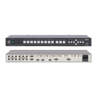
6 Connecting your Presentation Switcher / Scaler
To connect
1
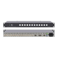
Figure 3 the VP-728 as illustrated in the example in , do the
following
2
1. Connect the following video sources
:
3
A component video
:
4
An s-Video source (for example, a DVD player) to the UNIV. IN 4 RCA
connectors, Y/CV and P
B/C
source (for example, a DVD player) to the UNIV.
IN 1 RCA connectors, Y/CV, P
B/C and PR
A computer graphics source to the UXGA 1 IN 15-pin HD computer
graphics video connector
An HDMI source (for example, a DVD player) to the HDMI 1 IN
connector
A graphics data source (for example, JPEG files from a PC or a USB
flash drive) to the USB connector on the front panel of the machine (not
illustrated in
Figure 3)
2. Connect the unbalanced stereo or digital audio sources
5
Figure 3
(not illustrated in
):
The audio of the component video source 1 to the AUDIO UNIV IN 1
S/PDIF RCA connector
The audio of the s-Video source 4 to the AUDIO UNIV IN 4 L and R
RCA connector
The audio of computer graphics source to the AUDIO UXGA 1 3.5mm
mini jack
3. Connect the video outputs:
The HDMI OUT connector to an HDMI acceptor (for example, a plasma
display)
The UXGA OUT 15-pin HD computer graphics video connector
6
4. Connect the AUDIO OUT L and R unbalanced stereo audio output and/or
the S/PDIF digital audio output to audio acceptors, for example, speakers
(not illustrated in
to a
video acceptor (for example, an analog display)
Figure 3).
1 Although this example shows only several inputs that are connected, you can connect all the inputs simultaneously
2 Switch OFF the power on each device before connecting it to your VP-728. After connecting your VP-728, switch on its
power and then switch on the power on each device
3 You do not have to connect all the inputs
4 Sometimes called YUV, or Y, B-Y, R-Y, or Y, Pb, Pr
5 As required. Not all devices need to be connected
6 In the HDTV mode, the signal goes out via three PINS: PIN 1 is Red or Pr, PIN 2 is Green or Y, PIN 3 is Blue or Pb
 Loading...