Important Settings for Film Tying
19
Pos: 6.5 /Überschrift en/Überschrift en 2/P-T/R/R ückhalteka mm bei Folienbind ung einstellen @ 396\mod _144671451991 0_78.docx @ 28 18558 @ 2 @ 1
3.1 Setting the Retaining Comb for Film Tying
Pos: 6.6 /Beip acks/Rundballe npressen/Folienbin dung/Modulgr uppen Umbau 2015/ZBBP1971, ZBBP1998: Rüc khaltekamm montieren @ 475\mod_ 1473074436515_78. docx @ 320 9172 @ @ 1
Fig.
Fig.
Pos: 6.7 /Beip acks/Rundballe npressen/Folienbin dung/Modulgr uppen Umbau 2015/ZBBP1999: Rückhalteka mm montieren @ 475\mod_ 14730748240 19_78.docx @ 32 09203 @ @ 1
Fig.
Pos: 6.8 /Beip acks/Rundballe npressen/Folienbin dung/Modulgr uppen Umbau 2015/Beschreibung 3: Rückhalte kamm montier en @ 387\ mod_1445261 043920_78.doc x @ 2775004 @ @ 1
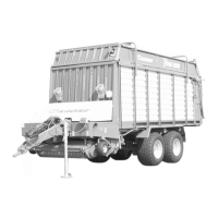
The trapezoidal rubbers (x) on the bottom side of the retaining comb are premounted with the
short side to the rear in direction of travel. (A)
If the blue strips (y) of the first net feed roller are taken along delayed or if they are not taken
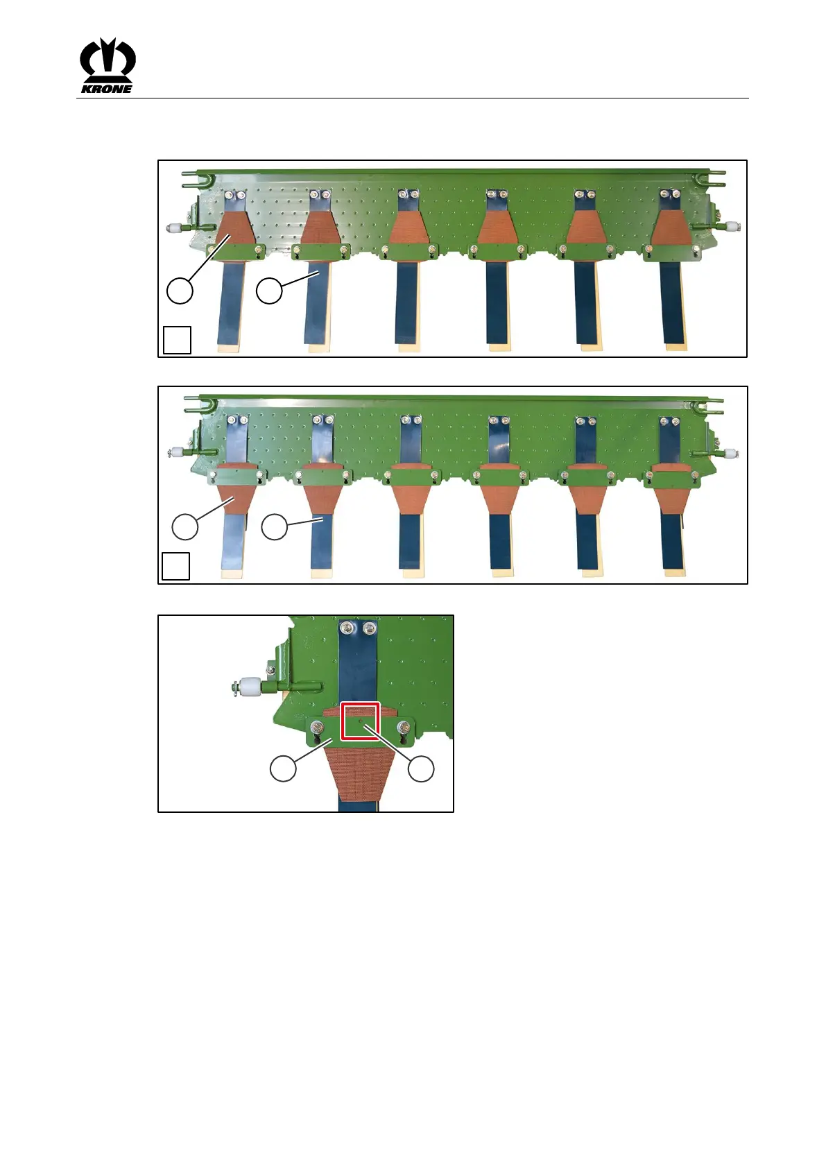
along, turn the trapezoidal rubbers (x) (B). This will allow for additional support:
• Unscrew the hexagon head screws on all trapezoidal rubbers.
• Dismount the sheet strip on all trapezoidal rubbers.
• Turn all trapezoidal rubbers (x) so that the short side points towards the front (B) in
direction of travel.
• Mount sheet strip with hexagon head screws.
Mind the correct alignment of the sheet strips (z). The borehole (u) on the sheet strip (z) shows
in the direction of the retaining comb.
Pos: 6.9 /Layout Module /---------------Seitenumbruch---------------- @ 0\mod_1196175 311226_0.doc x @ 4165 @ @ 1