Do you have a question about the Krone Comprima CF 155 XC and is the answer not in the manual?
Specifies the round baler types for which these operating instructions are valid.
Defines the intended audience for the document.
Explains navigation using table of contents, index, and cross-references.
Explains the meaning of graphical symbols used in the operating instructions.
Details hazard warning symbols (Danger, Warning, Caution) and their effects.
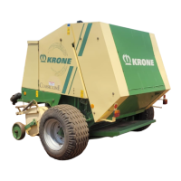
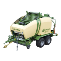
Describes the intended purpose and function of the Krone round balers.
Specifies the exclusive use of the round baler in agricultural work.
Covers fundamental safety rules, personnel qualification, danger zones, and specific activity dangers.
Outlines essential safety procedures for machine operation, stopping, securing, coupling, and uncoupling.
Explains the location and meaning of safety stickers on the machine for hazard awareness.
Introduces safety devices, hazard warnings, and the purpose of safety signs.
Details the importance of functional safety equipment and checks before start-up.
Lists parts included loose and outlines preparation steps before the first start-up.
Provides instructions for removing the transport tensioning device before operation.
Explains how to adjust the drawbar height and hitch for optimal working.
Covers PTO shaft length adjustment and mounting procedures for safe connection.
Details the installation procedure for the hose holder assembly.
Provides critical safety warnings and steps for hitching the machine to the tractor.
Covers special safety instructions for connecting and handling hydraulic lines.
Explains the function and connection of the hydraulic brake for export versions.
Outlines safety precautions and steps for installing the PTO shaft.
Details the procedure for connecting compressed air lines for the brake system.
Explains how to connect the machine's electrical systems, including the terminal.
Refers to separate operating instructions for installing the terminal in the tractor cabin.
Explains the function and safety implications of the ISOBUS short cut button.
Details the connection procedure for the multi-function lever to the CCI terminal.
Provides instructions for connecting the multi-function lever to the CCI terminal without integrated ISOBUS.
Explains how to power the terminal on and off when not connected to the machine.
Details the procedure for switching the terminal on and off when connected to the machine.
Describes the main display screen and its status line elements.
Explains how to adjust bale firmness settings for the Comprima CF 155 XC.
Details how to adjust the target bale diameter for Comprima CV150XC.
Explains how to adjust the target bale diameter for Comprima CV 210 XC.
Explains information messages that may appear on the terminal display.
Provides a short overview of the menu structure and navigation.
Lists the main menus and their sub-menus for quick reference.
Guides on how to navigate through different menu levels using function keys.
Introduces the "Settings" main menu and its sub-menus.
Explains how to access and navigate the "Baler setting" menu.
Details the procedure for adjusting bale diameter for specific models.
Explains how to set the number of net winds for wrapping.
Guides on adjusting the sensitivity of the direction display for specific models.
Explains how to set the pre-signalling time delay for bale readiness.
Describes how to correct bale size or filling based on predefined ranges.
Details how to set the time delay between bale readiness and tying process start.
Introduces the "Wrapper setting" menu and its sub-menus.
Explains how to adjust the number of net layers applied to the bale.
Guides on adjusting the number of film wrappings for the bale.
Describes the different operating modes for the wrapper function.
Explains the different operating modes for the swivel table.
Details how to set the sheet width for wrapping.
Explains the settings for sheet tear monitoring and control.
Introduces the "Counters" main menu and its sub-menus.
Explains how to activate and manage customer counters for bale production.
Describes the total bale counter and how to delete season counters.
Introduces the "Manual operation" main menu for direct machine control.
Details manual operation functions for the baler with an open bale chamber.
Lists and explains possible status messages for manual operation modes.
Guides on manually positioning the machine for tying.
Explains manual activation of the wrapping table for specific models.
Details manual operation for moving the lifter up or down.
Explains how to open and close the bale chamber using softkeys.
Guides on manually moving the swivel table to different positions.
Explains manual operation functions for the wrapper with a closed bale chamber.
Details how to open, close, and release the holding arms.
Explains how to switch the wrapping arm on and off.
Guides on moving the wrapping arm to its zero position.
Details manual operation for the wrapping arm on specific models.
Explains how to adjust the height of the wrapping arms.
Guides on moving the wrapping arm to its parking position for transport.
Lists and explains error messages related to manual operation.
Introduces the "Service" main menu and its sub-menus.
Explains how to perform a manual test and adjustment of machine sensors.
Describes the process and safety precautions for testing machine actuators.
Guides on performing manual tests on machine actuators for error detection.
Explains how to access and use the diagnostics menu.
Details manual operations that can be performed without a confirmation prompt.
Introduces the "Information" main menu, displaying software versions.
Introduces the password-protected "Technician" main menu.
Introduces the "ISOBUS" main menu and its password query.
Explains how to access and navigate the Virtual Terminal menu.
Guides on adjusting the display brightness for day and night modes.
Details the use of softkeys on ISO terminals with less than 10 keys.
Explains how to switch between connected ISOBUS terminals.
Guides on accessing ISOBUS diagnostics.
Explains how to use the joystick for auxiliary functions within diagnostics.
Lists necessary settings and checks to perform before starting work.
Provides guidance on recommended travelling speeds and conditions.
Explains how to achieve consistent bale density by evenly filling the bale chamber.
Details measures to reduce pressure on bale chamber side walls for critical forage.
Describes the assembly of additional bars for enhanced bale turning protection.
Explains the installation of ejector plates to aid bale ejection.
Covers procedures for tying bales and depositing them onto the swivel table or ground.
Outlines checks and preparations to be done before the baling process.
Provides instructions for detaching the bale cloth before baling.
Explains how to tension the floor conveyor before starting the PTO shaft.
Covers procedures to be performed after completing baling work.
Details how to release tension on the floor conveyor after baling.
Explains the function of the cam-type clutch for overload protection.
Describes the drive chain and overload protection for the pick-up.
Covers the default settings and adjustments for the pick-up working height.
Explains how to set the pick-up working height based on ground conditions.
Details how to adjust the pick-up bearing pressure using springs and chains.
Explains the function and adjustment of the roller crop guide for even crop collection.
Provides instructions for adjusting the baffle plate height based on crop conditions.
Covers general aspects of the cutting system, including its function and mechanical/hydraulic switching.
Describes the cutting system's components and capabilities for bale processing.
Explains how cutting length is determined by the number of blades and how to adjust it.
Details the procedure for setting the zero position of the cutter and tailgate safety.
Provides instructions for setting the net brake to the correct dimension.
Explains how to release the net brake to remove the net.
Describes the central chain lubrication system and how to adjust its delivery rate.
Emphasizes using authentic KRONE spare parts and following maintenance intervals.
Provides a table of maintenance tasks, intervals, and machine parts.
Details the procedure for setting the scraper rail relative to the spiral roller.
Shows the locations and specifications of various sensors on the machine.
Guides on adjusting Namur sensors and other sensors for correct operation.
Specific instructions for adjusting Namur sensors with a 12mm diameter.
Specific instructions for adjusting Namur sensors with a 30mm diameter.
Details how to set the sensor position for the cutter base.
Explains how to check and adjust axial play in the net brake system.
Provides a table of tightening torques for various thread sizes.
Lists tightening torques specifically for countersunk screws.
Discusses brake adjustment for tandem axles based on factory settings.
Guides on adjusting brakes using the hydraulic linkage setter.
Covers warnings and procedures for incorrect tyre fitting.
Provides instructions for checking wheel nuts, tyre pressure, and maintenance.
Lists recommended tyre air pressures for different tyre designations and conditions.
Covers safety and maintenance related to the drawbar and hitches.
Discusses wear limits, replacement, and proper coupling of towing rings.
Explains how to check oil levels and the intervals for oil changes in gearboxes.
Provides specific intervals for oil level checks and changes for machine gearboxes.
Lists filling quantities and recommended lubricants for various gearboxes.
Details oil level checks and oil changes for the main drive gearbox.
Explains the procedure for performing oil level checks and changes on slip-on gears.
Provides instructions and material numbers for screw connections on floor conveyors.
Describes the Novo Grip belts and the need for regular fringe removal.
Explains how to check and lubricate safety rollers for the single blade locking device.
Outlines checks and maintenance procedures for the rear floor conveyor.
Details the steps for adjusting the deflection roller.
Explains how to tension the wrapping table chain correctly.
Covers general information and safety precautions regarding drive chains.
Provides instructions for tensioning drive chains for various components.
Details how to check and correct chain tension for the front floor conveyor drive.
Explains how to check and correct chain tension for the rear floor conveyor drive.
Provides instructions for checking and correcting chain tension for the pick-up drive.
Details how to check and correct chain tension for the conveyor auger drive.
Explains how to check and correct chain tension for the roller drive.
Describes how to adjust the wrapping arm bearing if there is excessive play.
Covers safety precautions and procedures for working with the hydraulic system.
Explains the operation of the shut-off valve for tailgate safety.
Details safety procedures and components of the on-board hydraulic system.
Provides information on hydraulic tank filling quantities, oil designations, and disposal.
Details the procedure for changing the ventilation filter on the hydraulic tank.
Guides on replacing the hydraulic oil filter and checking the contamination indicator.
Explains the function and manual activation of electromagnetic valves.
Outlines safety precautions and procedures for grinding blades.
Covers safety and maintenance for the brake system, including adjustments and repairs.
Explains the installation, maintenance, and replacement of coupling heads.
Details the function, removal, and installation of the air filter for pipelines.
Provides instructions for inspecting and emptying the compressed-air reservoir.
Lists recommended lubricating greases and oils based on manufacturer and type.
Discusses different lubrication systems and the importance of using correct greases.
Guides on lubricating the PTO shaft at specified intervals.
Details the decomposition and assembly of the Walterscheid cam-type clutch.
Provides a table listing lubrication points, grease nipples, and intervals for the left and right sides.
Provides comprehensive instructions for cleaning, lubricating, and storing the machine after the harvest season.
Outlines essential checks and procedures before the new operating season begins.
Details specific maintenance tasks to be performed before the new season.
Explains how to vent the overload coupling after extended downtimes.
Provides a table listing common malfunctions, their possible causes, and remedies.
Details malfunctions related to the central chain lubrication system and their solutions.
Lists malfunctions of the wrapping mechanism, their causes, and remedies.
Refers to the KRONE ISOBUS Terminal chapter for error message descriptions.
Provides guidelines for the proper disposal of machine components, fluids, and materials.
Contains hydraulic system circuit diagrams for specific machine models.
Provides the electrical circuit diagram for the machine.
| Brand | Krone |
|---|---|
| Model | Comprima CF 155 XC |
| Category | Lawn and Garden Equipment |
| Language | English |