Maintenance
283
Pos: 59.30 /Übersc hriften/Überschri ften 3/A-E/E/Einste llung der Sensoren @ 0\mod_119 9962173428_78.doc x @ 37635 @ 33 @ 1
13.4.1 Adjusting the Sensors
Pos: 59.31 /BA/W artung/Sensoren/Namursen sor d = 12 mm @ 0\mod_119996224703 8_78.docx @ 37654 @ 44 @ 1
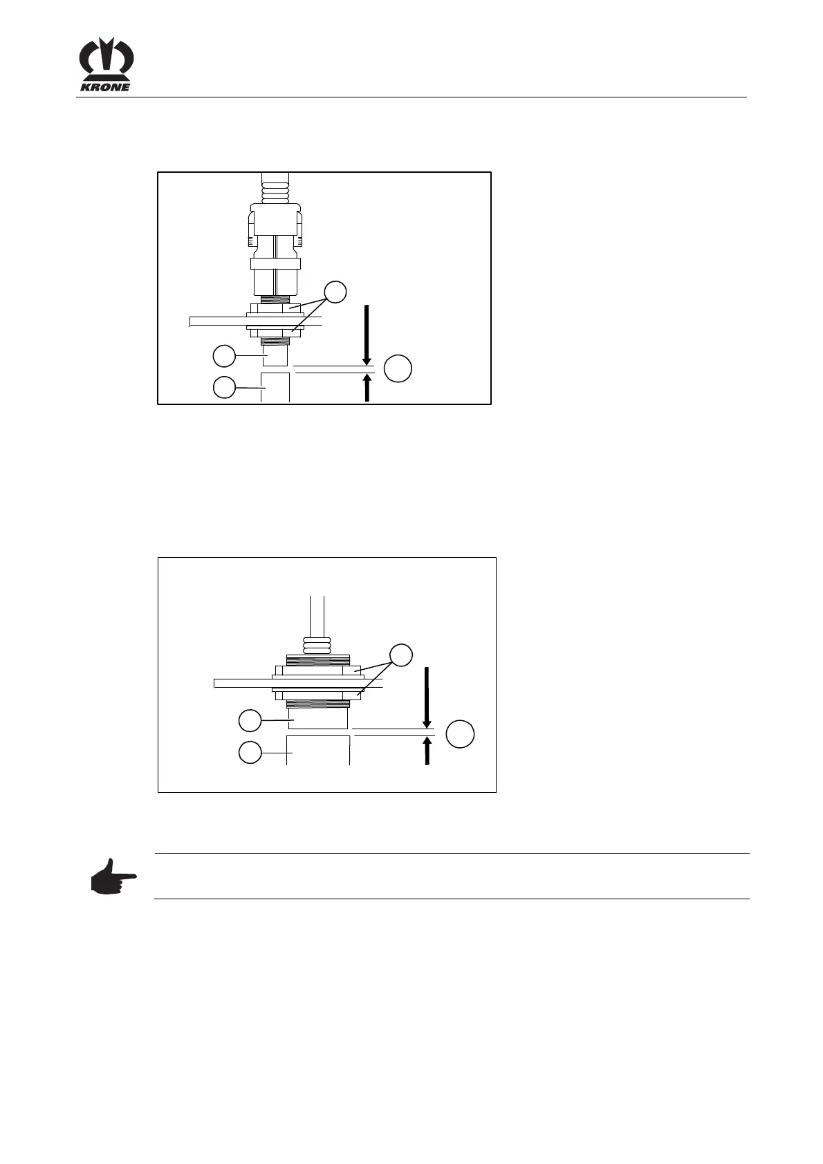
13.4.1.1 Namur sensor d = 12 mm
a
BP-VFS-088-1
2
1
3
Figure 221
The dimension between the encoder (2) and the sensor (1) must be "a" = 2 mm
.
Setting
• Loosen the nuts on either side of the sensor.
• Turn the nuts until dimension "a" = 2 mm
is reached.
• Tighten the nuts again.
Pos: 59.32 /BA/W artung/Sensoren/Namursen sor d = 30 mm CF/CV @ 75\mod_130935331 5461_78.docx @ 662557 @ 44 @ 1
13.4.1.2 Namur Sensor d = 30 mm
a
BPXC0172
2
1
3
Fig. 222
The dimension between the encoder (2) and the sensor (1) must be "a" = 4 mm .
Note
The dimension must be set to 2 mm for sensor “Net runs” (B2).
Setting:
• Loosen the nuts on both sides of the sensor.
• Turn the nuts until dimension "a" = 4 mm is reached.
• Tighten the nuts again.
Pos: 59.33 /Layout Module /---------------Seitenumbruch---------------- @ 0\mod_1196175311226_0. docx @ 4165 @ @ 1