Operation of the Hydraulic Zero Setting of Blades (Optional)
204
Pos: 53.5 /Überschri ften/Überschri ften 2/K-O/KRONE ISOBUS- Terminal @ 212\mod_1389780 572708_78.docx @ 174224 2 @ 22 @ 1
10.1 KRONE ISOBUS Terminal
Pos: 53.6 /Überschri ften/Überschri ften 3/F-J/Grundbild bei hy dr. Messernullscha ltung (Option) @ 82\mod_1 316609023251_78.doc x @ 720331 @ 33 @ 1
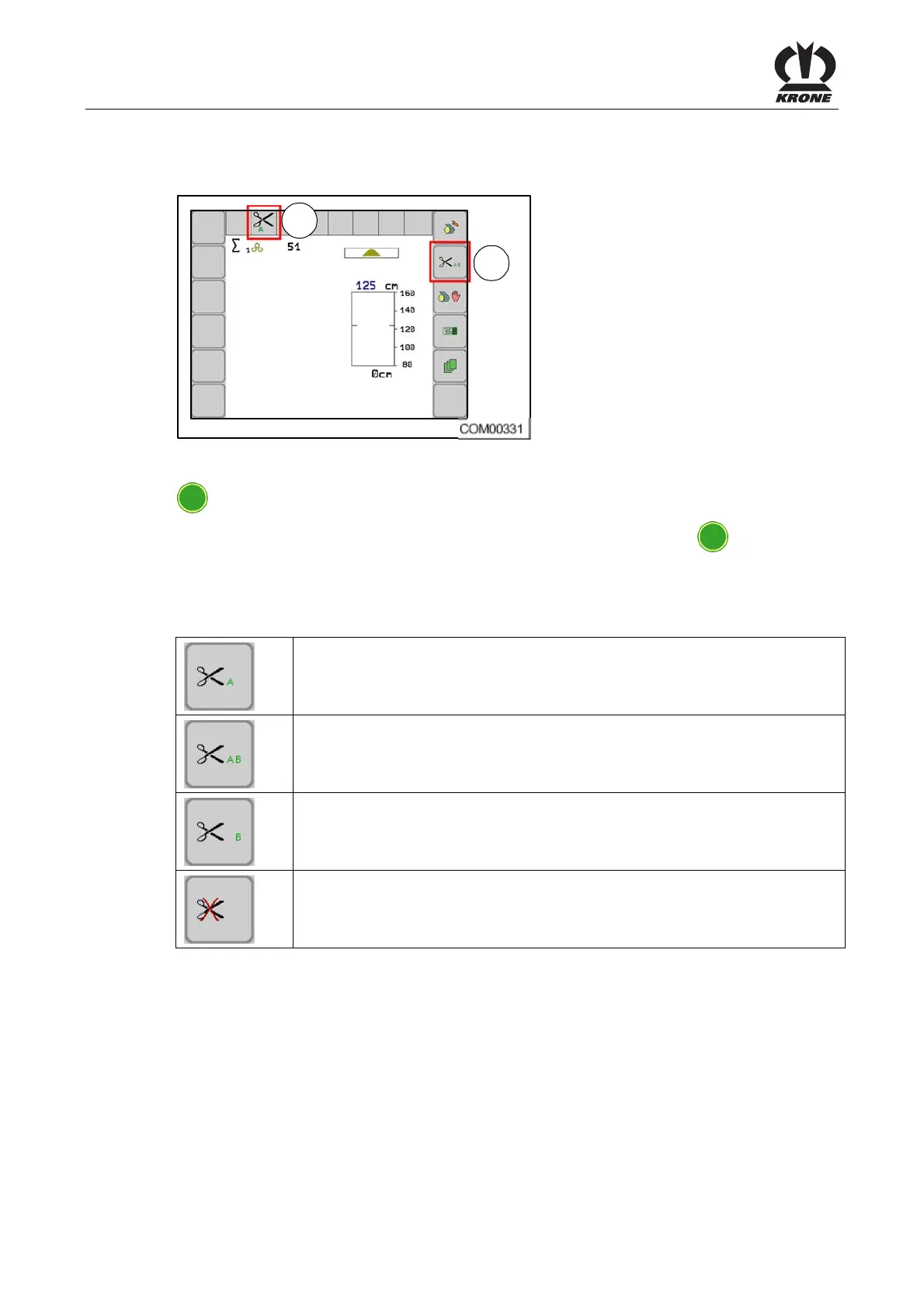
10.1.1 Basic screen in case of a connected zero setting of blades (option)
Pos: 53.7 /BA/Inf o-Center/Rundballenpr esse/Hand-/Auto matikbetrieb/Grun dbild bei Messernullsc haltung CCI @ 173\mod_137 0942854309_78.doc x @ 1483541 @ @ 1
2
1
Fig. 151
In the basic screen, it is possible to select between the different blade group control systems via
F2
key. In this process, the selection sequence is defined as shown in the table.
The selected blade group control system is shown in the display next to the
F2
key (2).
The status of the blade group control system is shown in the display in display (1).
Selection options blade group control system
Swivelling in blade group A (activating)
Swivelling in blade group A and B (activating)
Swivelling in blade group B (activating)
Swivelling out blade group A and B (deactivating)