20
KHF - SERIES A FAN COIL UNITS
INSTALLATION, OPERATION, AND MAINTENANCE MANUAL
GENERAL
Each unit on a job will have its own unique operating
environment and conditions that may dictate a maintenance
schedule for that unit that is different from other equipment
on the job. A formal schedule of regular maintenance and
an individual unit log should be established and maintained.
This will help to achieve the maximum performance and
service life of each unit on the job.
Information regarding safety precautions contained
in the preface at the beginning of this manual should
be followed during any service and maintenance
operations.
For more detailed information concerning service operations,
consult your Sales Representative or the Factory.
MOTOR/BLOWER ASSEMBLY
The type of fan operation is determined by the control
components and their method of wiring, and may vary from
unit to unit. Refer to the wiring diagram for each unit for
that unit’s individual operating characteristics. Motors are
permanently lubricated, PSC or EC type and do not require
field lubrication.
!
Caution
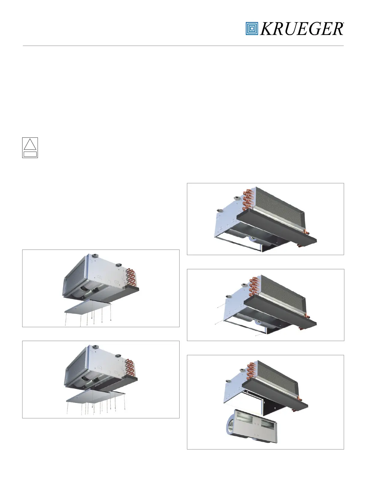
Figure 5a
Figure 5b
Figure 5a-5b: Bottom panel removal
SECTION THREE - NORMAL OPERATION & PERIODIC MAINTENANCE
FAN DECK
The fan assembly is easily removed from the unit without
disconnecting the ductwork for service access to motors and
blowers at, or away from the unit.
Should the assembly require more extensive service, the
motor/ blower assembly may be removed from the unit to
facilitate such operations as motor or blower wheel/housing
replacement, etc. Dirt and dust should not be allowed to
accumulate on the blower wheel or housing. This can result
in an unbalanced blower wheel condition that can damage
a blower wheel or motor. The wheel and housing may be
cleaned periodically using a vacuum cleaner and a brush
taking care not to dislodge the factory balancing weights on
the blower wheel blades.
Figure 6a
Figure 6b
Figure 6c
Figure 6a-6c: Fan deck removal

 Loading...