30
KHF - SERIES A FAN COIL UNITS
INSTALLATION, OPERATION, AND MAINTENANCE MANUAL
INSTALLATION, OPERATION AND MAINTENANCE
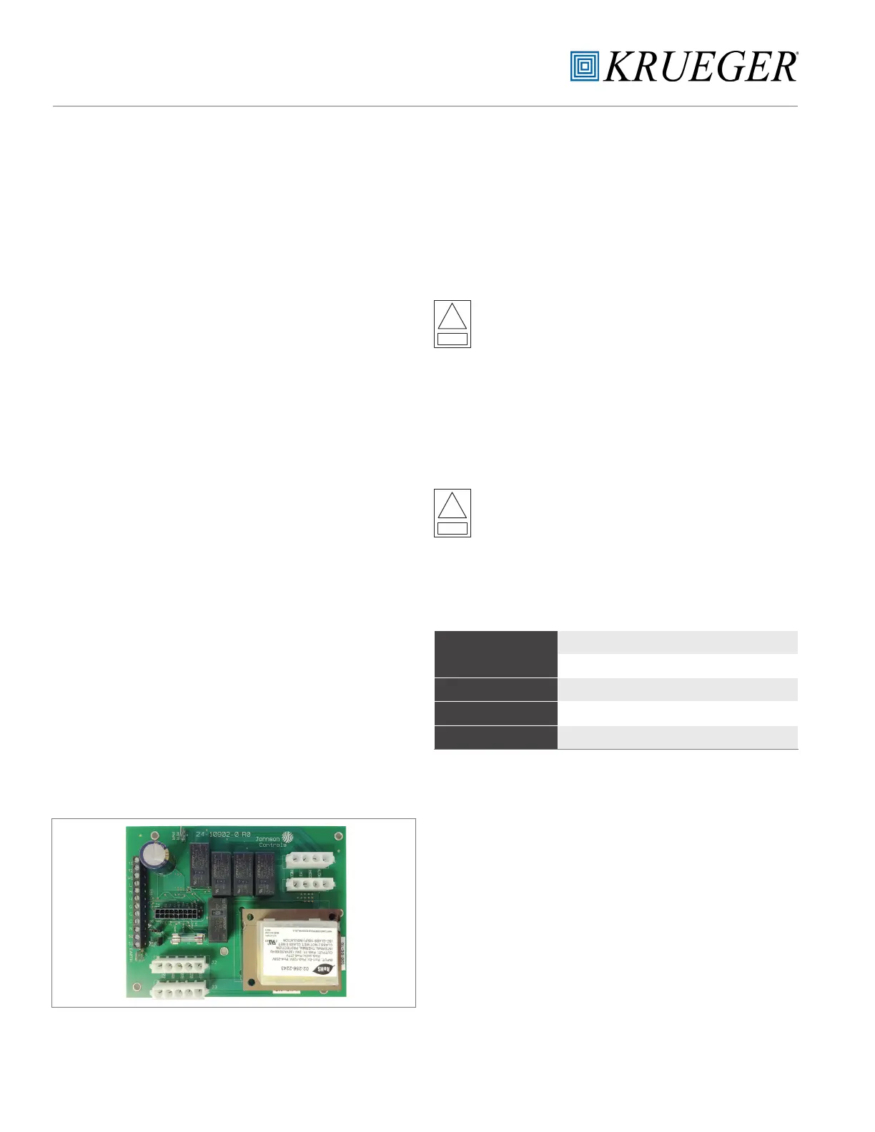
The Fan Relay Board assembly (FRBii) provides electronic
control for the fan motor and various connections for
peripheral devices. The FRBii accepts incoming single phase
power of nominal AC voltages 120, 208, 240 and 277. The
assembly includes a multitap transformer (30VA or 50VA)
that steps each of these primary voltages to 24 VAC. The
assembly allows for the control of a three speed fan motor,
including a relay for control of the neutral voltage signal
path.
The FRBii can be connected to an external device (e.g.,
thermostat, controller, 3-speed switch) to control the three
fan speeds. The FRBii includes logic to detect when multiple
speeds are commanded simultaneously and block all but
the highest of the commanded speeds from being sent to
the motor windings. A signal to call for electric heat from
an external controller will verify that a fan speed is selected
before providing the command signal to the external electric
heat control to ensure that electric heat can only be energized
when the fan motor is operational. The assembly includes
factory provided harnesses to allow for faster installation
and improved troubleshooting by the end user.
The FRBii allows for peripheral devices (e.g., thermostat
controllers, electric heat relays, water valve actuators,
condensate drain pan float switches, air dampers) to be
connected by either the OEM or by the installer. The fan
relay board also includes a fuse on the secondary side of the
transformer to protect against incorrect wiring of external
components, shorting the transformer leads. The signals in
the screw terminal block (TB1) and 18-pin black connector (J1)
have a nominal voltage of 24VAC. These signals are properly
insulated from line voltage present on the assembly (J2-J5).
transformer to protect against incorrect wiring of external
components, shorting the transformer leads.
The signals in the screw terminal block (TB1) and 18-pin
black connector (J1) have a nominal voltage of 24VAC. These
signals are properly insulated from line voltage present on
the assembly (J2-J5).
Figure F.1: Fan Relay Board (FRBii)
INSTALLATION
MOUNTING
Important: Do not overtighten the screws. Overtightening
may strip the threads and will void the warranty.
Using #8-3/4” screws (quantity six), install the assembly
using the provided standoffs.
Risk of Electric Shock: Disconnect or isolate all power
supplies before making electrical connections. More
than one disconnection or isolation may be required
to completely de-energize equipment. Contact with
components carrying hazardous voltage can cause
electric shock and may result in severe personal
injury or death.
WIRING
Install the wiring so it does not cause a hazard, and is
protected against electrical and mechanical damage.
Risk of Electric Shock: Ground the FRBii according
to local, national, and regional regulations. Failure
to ground the FRBii may result in electric shock and
severe personal injury or death.
Ground the assembly from the EARTH terminal (W2) to the
enclosure.
!
Warning
!
Warning
Ratings
MODEL(S)
30VA – PC-01-0134 PK-FCU030-0 (25-3043-7)
50VA – PC-01-0135 PK-FCU050-0 (25-3043-15)
VOLTAGE 120 through 277VAC
CURRENT (FAN RELAYS) 12A
OPERATING TEMPERATURE -4°F to 140°F (-20°C to 60°C)
SECTION FIVE: FAN RELAY BOARD