25
KHF - SERIES A FAN COIL UNITS
INSTALLATION, OPERATION, AND MAINTENANCE MANUAL
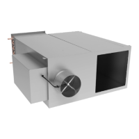
DISCHARGE AIR SENSOR
AIRFLOW MOUNTING LOCATION
FOR REAR RETURN UNIT
MOUNTING LOCATION
FOR BOTTOM RETURN UNIT
Figure 12a
ENVIRONMENT
(OUTSIDE OF UNIT)
UNIT’S FAN SECTION
(INSIDE OF UNIT)
VACUUM PORT
CHASSIS INSULATION
PRESSURE PORT
CHASSIS
DOUBLE SIDED TAPE
FILTER RETENTION TAB
Figure 12b
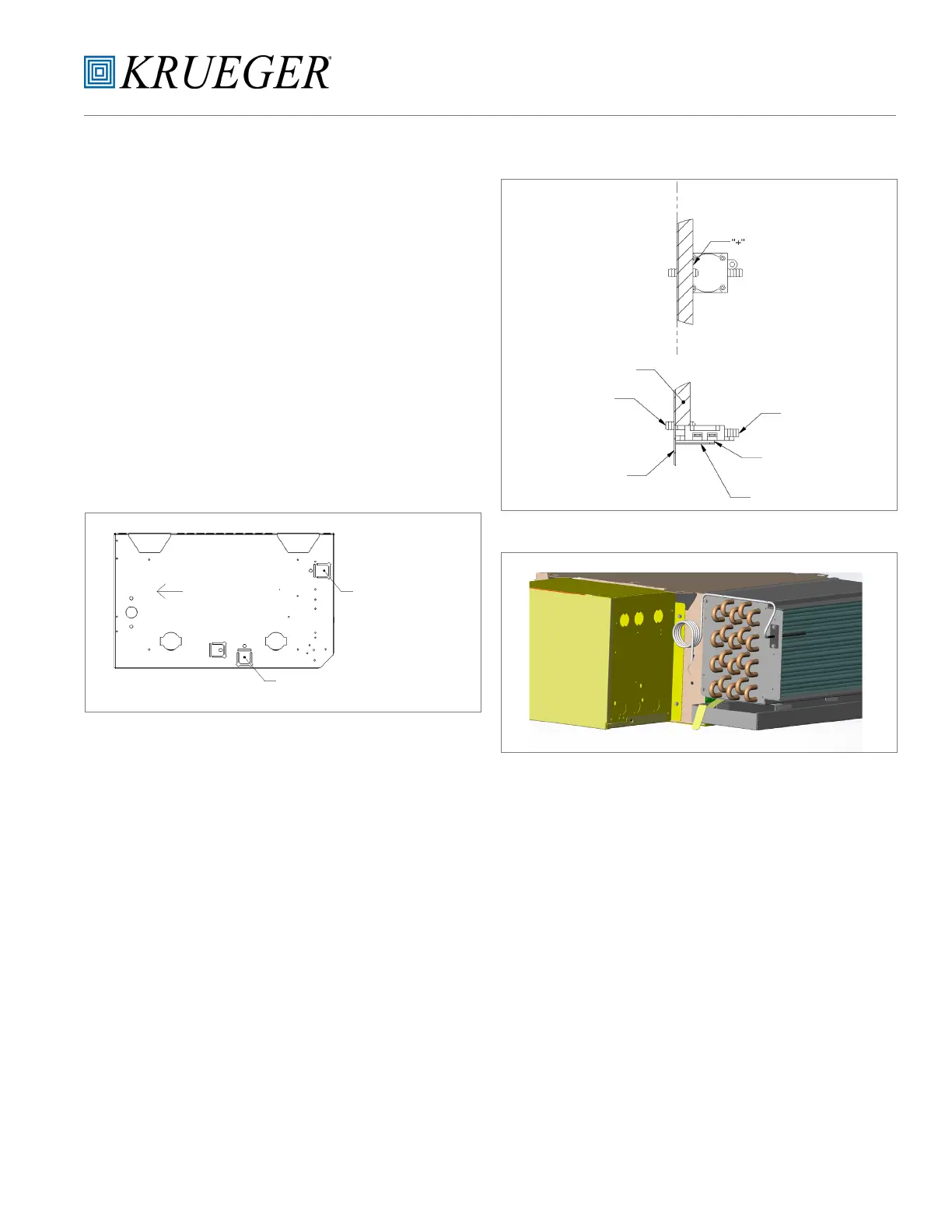
Figure 13
General Information
The Discharge Air Sensor is a nickel 1kΩ sensor probe with a
flanged mounting bracket (no enclosure).
Suggested Location
The Discharge Air Sensor is fitted to the side of the coil flange
in the holes provided for this accessory. (See Figure 13.)
Replacement Instructions
a. Disconnect the main power on the unit.
b. Mount the Discharge Air Sensor with two screws as
shown. (See Figure 13.)
c. Secure the plenum-rated cable into control enclosure
using the control enclosure knockouts accordingly.
d. Once all of the connections are made, reconnect the
main power.

 Loading...