23
KHF - SERIES A FAN COIL UNITS
INSTALLATION, OPERATION, AND MAINTENANCE MANUAL
TECHNICAL SPECIFICATIONS
OPERATION
VOLTAGE
120V +/- 10% ~50/60Hz – 4.7W
208 - 230V +/- 10% ~50/60Hz – 4.7W
OPERATING
TEMPERATURE
Max 257 °F (125 °C) auto-reset
THERMAL
PROTECTION
(OVERHEATING)
257 °F (125 °C) auto-reset
MAX HEAD 23 Ft
MAX SUCTION
LIFT
16.52 Ft
TUBING (NOT
INCLUDED)
Flexible tubing 1/4” ID, 3/8” OD
CONDENSATE WATER PUMP
SAFETY WARNING: Risk of electric shock. Make
certain that the entire power supply to the unit/
system is disconnected before attempting to install,
service or remove this component.
General Information
The high performance water condensate pump is suitable
for units up to 5.6 tons (67 kBtu - 20 kW). The piston
technology is specifically designed for removing condensate
from air conditioning systems. It is fully reliable, in any kind
of environment and its operating sound level will remain
silent <23 dB whatever the volume of condensate.
The condensate pump uses a temperature differential
between two measurements to determine if it runs. If there
is greater than 14°F between the measurements, the pump
runs. The cold sensor is placed on the chilled water supply
and the warm sensor is placed in the fan compartment. The
pump is capable of running without any water. Discharge
tubing is not factory provided and must be field provided
during the initial installation process.
!
Warning
TECHNICAL SPECIFICATIONS
WIRE SIZE 2.1–0.6 mm (12–22 AWG) diameter recommended
STATUS OUTPUT Switch normally open
SWITCH LOAD
CAPACITY
1 A at 30 VAC/42 VDC maximum
!
Warning
CURRENT SWITCH DEVICE
SAFETY WARNING: The Current Switch is intended
to provide an input to equipment under normal
operating conditions. Where failure or malfunction
of the Current Switch could lead to personal injury
or property damage to the controlled equipment
or other property, additional precautions must be
designed into the control system. Incorporate and
maintain other devices, such as supervisory or
alarm systems or safety or limit controls, intended
to warn of or protect against failure or malfunction
of the Current Switch.
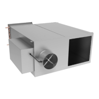
General Information
The Current Switch is a non-intrusive device that detects
current flowing through the motor power wire. Completely
self-powered, the Current Switch draws its power from
current induced by the power wire of the motor being
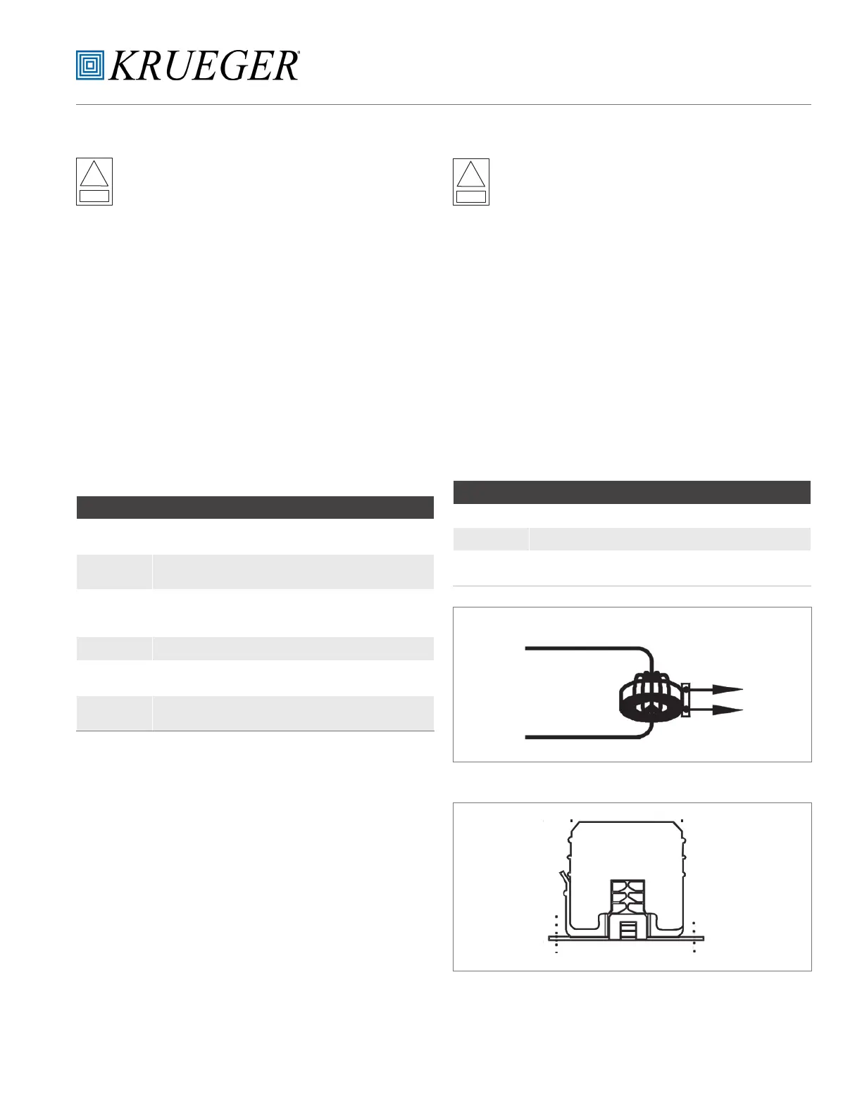
monitored. Fig. 5 shows the current switch wire connections.
It is panel mounted with two screws inside the main electrical
enclosure; refer to fig. 6.
Replacement Instructions
a. Disconnect the main power on the unit.
b. For wiring connection to unit, refer to unit wire diagram.
c. For accessories, assembly, and internal wire
connections, refer to condensate water pump
manufacturer instructions.
d. Locate the two alignment holes for the water pump
bracket, right bottom corner of the unit.
e. Attach pump to bracket and mount it to unit with two
screws. (See Figure 1)
f. Complete all assembly prior to mounting pump cover.
g. Connect flexible tubing (not supplied). Once all of the
connections are made, reconnect the main power of the
unit.
Figure 9 Current Switch in Circuit
OUTPUT
MOTOR POWER WIRE
Figure 10 Current Switch Mounting

 Loading...