33
KHF - SERIES A FAN COIL UNITS
INSTALLATION, OPERATION, AND MAINTENANCE MANUAL
TABLE F.5 – REPLACEMENT FUSE
TRANSFORMER FUSE
PART
NUMBER
MANUFACTURER
PART
NUMBER
30VA 2A PE-06-0000
Littelfuse 0235002.MXP
Bussmann BK/GMA-2-R
50VA 3A PE-06-0016
Littelfuse 0235003.MXP
Bussmann BK/GMA-3-R
TABLE F.6 – FIELD INSTALLED COMPONENT DESCRIPTIONS
NAME DESCRIPTION
Field-Provided
Float Switch
To install a oat switch, wire the oat switch leads into S1 and C on the crew
terminals. After wiring the oat switch, remove jumper JP2. The JP2 jumper
must be removed for the oat switch to operate correctly.
Note: If a oat switch was installed in the factory, the oat switch may be
connected through a factory-provided harnesses instead of wired to the
screw terminal.
Start/Stop
for the Fan
To start or stop the fan from an external controller, wire the leads for the
switch contacts that will be made or broken to R and G on the screw termi-
nals. After wiring the switch, remove jumper JP3.
Remote
3-Speed Switch
To add a remote 3-speed switch, wire the leads for the switch to G, H, M and L
on the screw terminals. After wiring the switch, remove jumper JP1.
Tools Required for Installation/Troubleshooting:
• Digital multimeter capable of measuring 30 volts AC
• Insulated 1/8” flat bladed screwdriver
• Fuse puller (optional)
• Mini hook test clips for multimeter (optional)
Fuse – A fuse is included on the secondary side of the
transformer to protect the transformer from incorrect
wiring of thermostat, controller, etc. that shorts the 24VAC
and COM. The fuse is a fast-acting glass body cylindrical
fuse (5x20mm). If tripped, replace the fuse by removing the
tripped fuse with fuse pullers and replace using one of the
below listed fuses.
Suggested fuse replacement information:
HEAT Output – The HEAT output connects to an electric heat
contactor or relay. This output represents the command
signal from the thermostat or controller on the W1 input.
The output is interlocked with the fan relays to ensure that
a fan speed is commanded when electric heat is requested.
DAMP Output – The DAMP output connects to a motorized
damper actuator used to control airflow from an external
source. This output provides 24VAC to energize the damper
actuator. This output is interlocked with the fan relays to
ensure that a fan speed is commanded before energizing
the damper actuator.
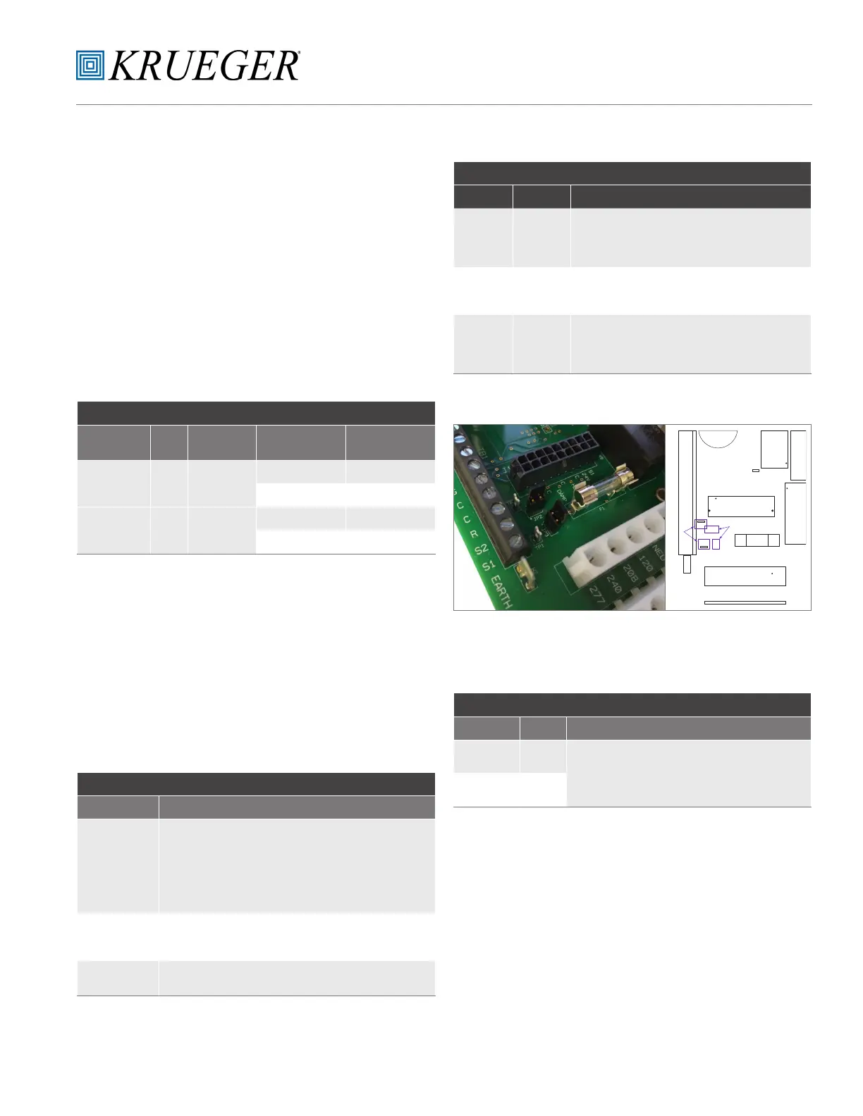
TABLE F.8 – TEST POINT DESCRIPTION
TEST POINT NAME DESCRIPTION
TP1 24VAC
These test points can be used to verify 24 VAC assuming incoming
voltage is within tolerance. They can be connected to with mini-
hook test clips for a digital multimeter. Test point locations for TP1
and TP2 can be seen in Figure F.3.
TP2 COM
TEST POINTS
JP2 and JP3 locations can be seen in Figure F.3.
TABLE F.7 – JUMPER DESCRIPTION
JUMPER NAME DESCRIPTION
JP1
Speed
Select
Jumper
This jumper is installed between 24V and HIGH when no three
speed switch is included (remote or unit mounted). The jumper will
be installed at the end of the harness connected to J1. If a three
speed switch is added later, JP1 must be removed.
JP2
Float
Switch
Jumper
This jumper is installed between S1 and C when a oat switch
is not installed. The jumper is removed when a oat switch is
installed.
JP3
Fan
Enable
Jumper
This jumper is installed between R and G/24V. The jumper is
removed when remote control of the fan motor is desired. In most
instances, JP3 will be installed (unless a thermostat or controller
is remotely controlling of the equipment).
JUMPERS
TP3
J1
F1
J2
TP2
JP2
TP1
JP3
W2
TEST
POINTS
JUMPERS
K1
TB1
Figure F.3: FRBii Jumpers and Test Points