7
KHF - SERIES A FAN COIL UNITS
INSTALLATION, OPERATION, AND MAINTENANCE MANUAL
If the valve package connection at the coil is made with a
union, the coil side of the union must be prevented from
twisting (“backed up”) during tightening to prevent damage
to the coil tubing. Over-tightening must be avoided to prevent
distorting the union seal surface and destroying the union.
Due to the diversity of valve packages for this product, install
the valve packages with no leaks or interference between
components during operation and maintenance. In the case
of field installed valves and piping, the chilled water valve
cluster (or metering device on DX units) should be installed in
such a way that any dripping or sweating is contained in the
auxiliary drain pan or other device. Valves and TXV’s should
be secured or supported to avoid damage to coil headers or
distributor tubes. All valves, pipes, and components must
be sufficiently supported to ensure structural integrity and
proper operation of the unit.
After the connections are completed, the system should
then be tested for leaks. Since some components are not
designed to hold pressure with a gas, hydronic systems
should be tested with water.
All water coils must be protected from freezing
after initial filling with water. Even if the system is
drained, unit coils may still hold enough water to
cause damage when exposed to temperatures
below freezing.
Refrigerant systems should be tested with dry nitrogen
rather than air to prevent the introduction of moisture
into the system. In the event that leaking or defective
components are discovered, the Sales Representative must
be notified BEFORE any repairs are attempted. All leaks
should be repaired before proceeding with the installation.
!
Caution
COOLING/HEATING MEDIUM CONNECTIONS
Toxic residues and loose particles resulting from
manufacturing and field piping techniques such
as joint compounds, soldering flux, and metal
shavings may be present in the unit and the piping
system. Not for use with domestic or potable water
systems.
Submittals and Product Catalogs detailing unit operation,
controls, and connections should be thoroughly reviewed
BEFORE beginning the connection of the various cooling
and/or heating mediums to the unit.
All accessory valve packages should be installed as required,
and all service valves should be checked for proper
operation. To prevent condensation accumulation and
runoff, chilled water valve packages must be insulated, or
preferably, utilize a factory-provided auxiliary drip tray.
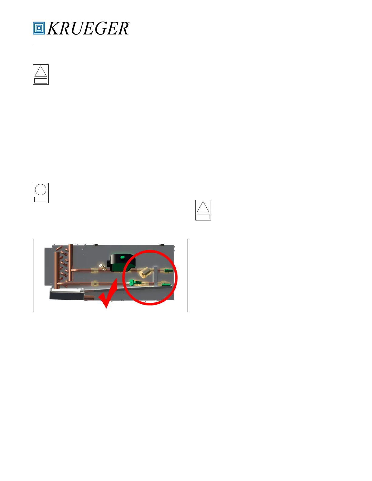
Before brazing or sweating valve packages and their
components into place, it is critical to pre-check all
valve package clearances in relation to the auxiliary
drain pan. If the auxiliary drain pan cannot be
properly affixed to the auxiliary drain pan support
bracket, adjust valve package component angles
until proper clearance is achieved.
!
Caution
!
Note
If coil and valve package connections are to be made with
“sweat” or solder joint, care should be taken to assure that
no components in the valve package are subjected to a high
temperature which may damage seals or other materials.
Many two-position electric control valves, depending on
valve operation, are provided with a manual-opening lever.
This lever should be placed in the “open” position during
all soldering or brazing operations. Valve bodies should be
wrapped with a wet rag to help dissipate heat encountered
during brazing.
 Loading...