24
KHF - SERIES A FAN COIL UNITS
INSTALLATION, OPERATION, AND MAINTENANCE MANUAL
DIFFERENTIAL AIR PRESSURE SWITCH
ELECTRICAL TECHNICAL SPECIFICATIONS
INITIAL
RESISTANCE
<500mW
RATING
3.15ma @ 125VAC
10-20ma @ 5-24VDC
ADJUSTABLE SET POINT RANGES IN H
2
O
Ranges
In H
2
O
Min. Max. Proof
0.10 0.50 5.0
FUNCTIONAL TECHNICAL SPECIFICATIONS
Operating positing Diaphragm vertical, barbed ttings horizontal
Operating temp. -40 °F to 140 °F (-40 °C to 60 °C)
General Information
This accessory is a differential pressure switch with a
normally-open (NO) dry contact that is factory calibrated
to close at a differential pressure of 0.15 inches of water
or greater. The switch measures the pressure differential
between the unit’s fan section and the environmental
pressure outside the unit. When the filter is sufficiently
clogged or dirty, differential pressure will rise and the switch
will close.
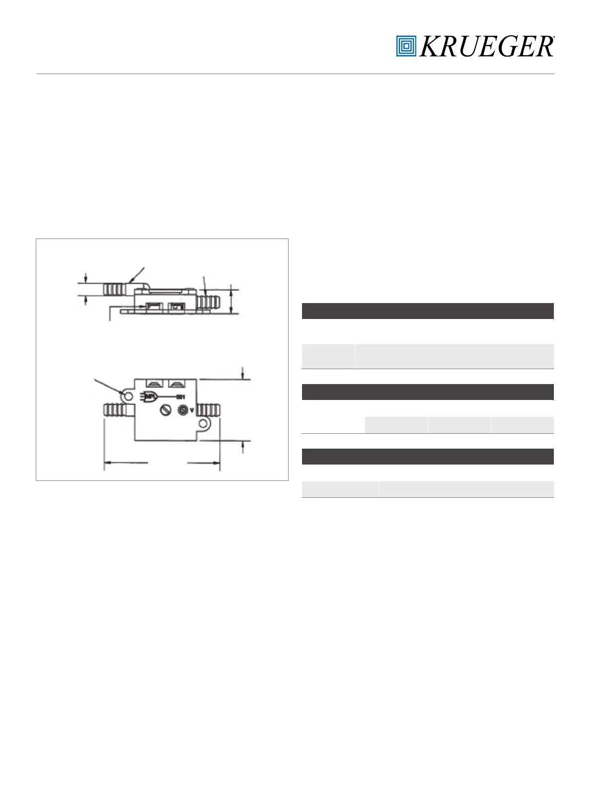
General Measurements: Pressure Switch
PRESSURE
PORT
VACUUM
PORT
.38” (9.65)
2x Ø
.2” (5.08)
TERMINALS
2x Ø
.125” (3.18)
1.88”
(47.75)
1” SQ.
(25.4)
Figure 11
Assembly
The differential air pressure switch is mounted inside the
unit with double sided tape behind the filter retention tab.
(See figure 12a). Instructions for commissioning or replacing
the differential air pressure switch:
a. Disconnect main power on the unit.
b. Secure differential air pressure switch on the filter
retention tab using double sided tape. Position the
pressure port (marked with “+”) outside the chassis
exposed to the environment. The vacuum port should
extend inside the chassis and be open to the unit’s fan
section. (See figure 12b.)
c. Wire the NO relay using .187 quick connectors.
d. Verify all connections before reconnecting main power.

 Loading...