26
KHF - SERIES A FAN COIL UNITS
INSTALLATION, OPERATION, AND MAINTENANCE MANUAL
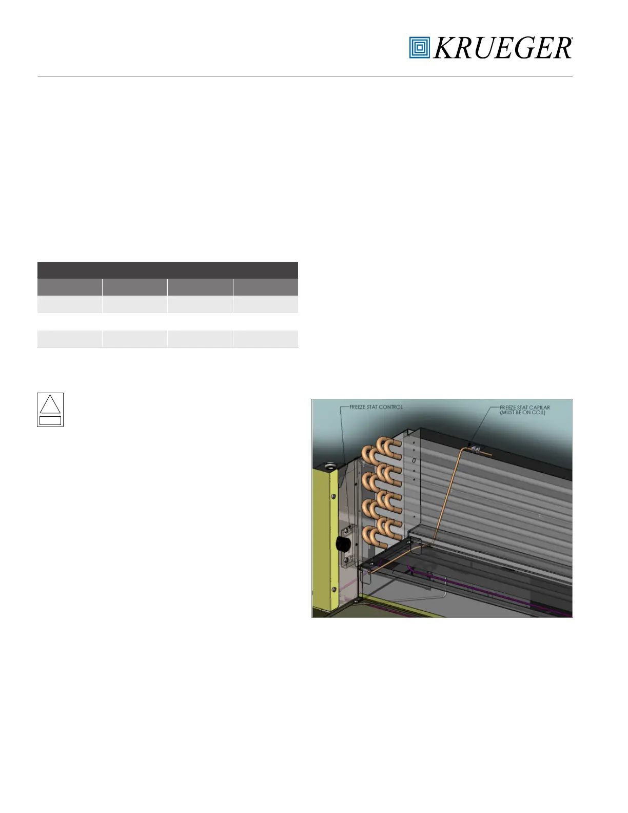
Figure 14
General Information
This low temperature device will de-energize the system
if the operating conditions begin to approach freezing (as
water freezes it expands and will rupture the coil barrel
tubes). The function of this low temperature device is to
cycle a SPST switch in response to changes of temperature.
Refer to fig. 4 to locate the device on your unit.
Adaptable Cold Control
Range of adjustments are limited to the rotation of the dial
for the required temperature set point needed.
Replacement Instructions
The primary purpose of the low limit cutout is to prevent the
coil from freezing. Therefore, before mounting the control,
you need to consider all possible factors that help protect the
coil from freezing. It is important that the cutout capillary not
be cut, kinked or pinched in mounting to unit elements. Also,
ensure tubing clamps and wells are of compatible material
with the control sensing element to prevent corrosion.
a. Disconnect the main power on the unit.
b. Locate the two inner mounting holes between control
enclosure and coil.
c. Use two supplied screws to mount the low temperature
cutout in place.
d. Work your way back up to the bellows, stringing the
sensing element throughout the drain pan,
e. Position the sensing element horizontally across the face
of the coil, and secure the sensing element with mount
tape and wire tie. (See Figure 14.)
f. Wire the NC relay using the .250 quick connectors.
g. Once all of the connections are made, reconnect the
main power of the unit.
Electrical Ratings
WARNING: Do not exceed the maximum wattage,
ratings, or published operating conditions as noted
below.
!
Warning
ALTITUDE CORRECTIONS
FEET TURNS FEET TURNS
2000 35 8000 215
4000 100 9000 250
6000 160 10000 270
NOTE: Clockwise turns of range screw.
LOW TEMPERATURE CUTOUT CONTROL

 Loading...