9
KHF - SERIES A FAN COIL UNITS
INSTALLATION, OPERATION, AND MAINTENANCE MANUAL
DUCTWORK CONNECTIONS
All ductwork and/or supply and return grilles should
be installed in accordance with the project plans and
specifications. If not included on the unit or furnished from
the factory, Krueger supply and return grilles are available in
a variety of types.
Units can be configured from the factory with duct collars for
attaching ductwork. The factory suggests using galvanized
sheet metal ductwork or a flexible canvas attached to the
duct collars using sheet metal screws. Duct connections
should follow SMACNA standards and national and local
codes.
All units must be installed in non-combustible areas. Some
models are designed to be connected to ductwork with
a MINIMUM amount of external static pressure. Consult
the approved submittals and the product catalog for unit
external static pressure limitations.
Units provided with outside air for ventilation should have
some form of low temperature protection to prevent coil
freeze-up.
It should be noted that none of these methods would
adequately protect a coil in the event of power failure.
The safest method of freeze protection is to use glycol in
the proper percent solution for the coldest expected air
temperature.
The manufacturer assumes no responsibility for undesirable
system operation due to improper design, equipment or
component selection, and/or installation of ductwork,
grilles, and other field supplied components.
ELECTRICAL CONNECTIONS
The unit nameplate lists the unit electrical characteristics
such as the required supply voltage, fan and heater
amperage and required circuit ampacities. The unit wiring
diagram shows all unit and field wiring. Since each project
is different and each unit on a project may be different,
the installer must be familiar with the wiring diagram and
nameplate on the unit BEFORE beginning any wiring. This
unit is not acceptable for installation in hazardous/explosive
areas.
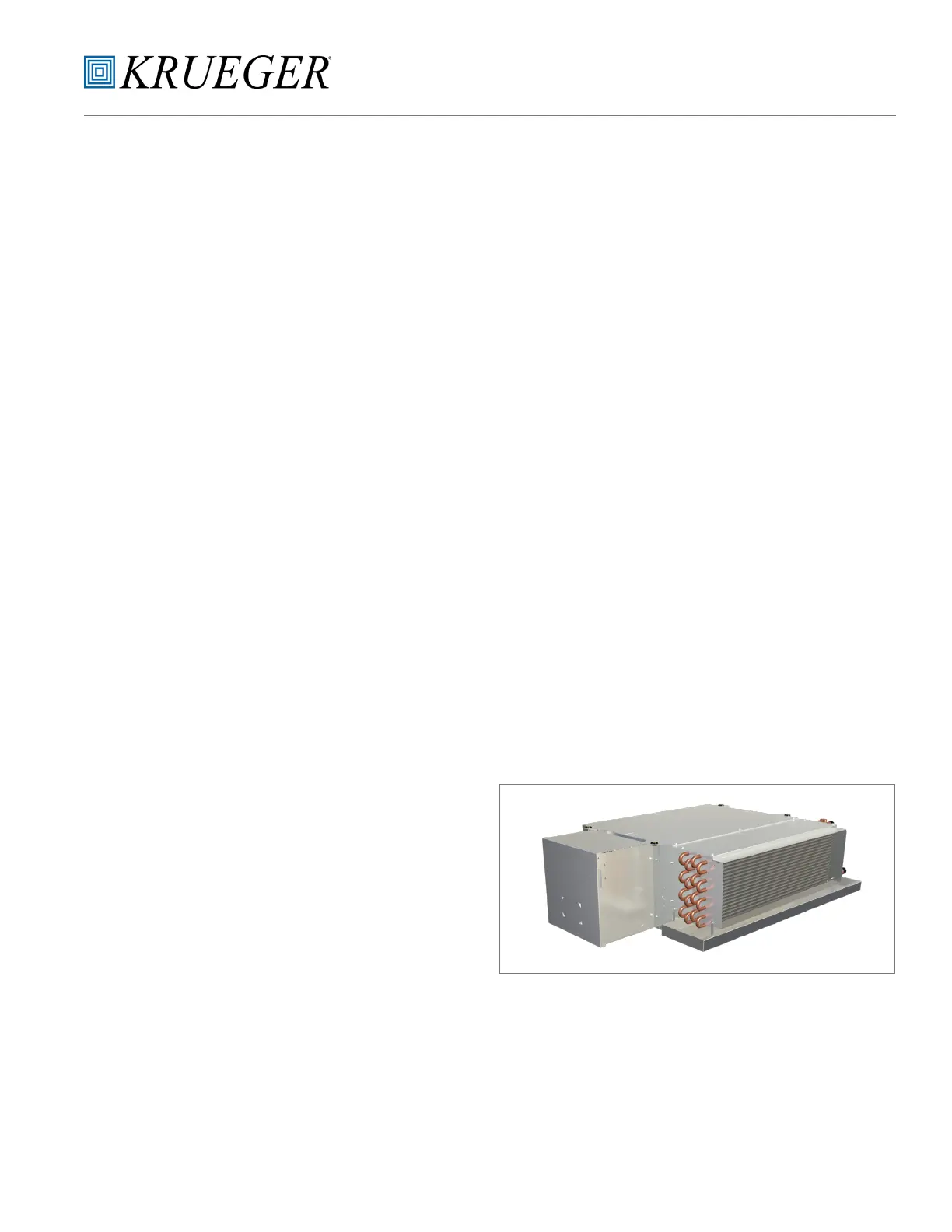
Figure 4: Electrical enclosure
ELECTRICAL ENCLOSURE
The electrical control enclosure provides access to the
electrical compartment. This compartment houses all
electric heat and control components. Terminal strips are
furnished for simple power and control wiring connections.
Multiple knockouts allow wiring entries from either side of
the compartment.
All components furnished for field installation, by either the
factory or the controls contractor should be located and
checked for proper function and compatibility. All internal
components should be checked for shipping damage. After
installation and before energizing the unit, verify voltage
and check that all electrical connections are tight. Electrical
connections should be periodically checked for tightness.
Any devices such as fan switches or thermostats that have
been furnished from the factory for field installation must
be wired in strict accordance with the applicable wiring
diagrams. Failure to do so could result in personal injury
or damage to components and will void all manufacturers’
warranties.
All field wiring should be done in accordance with governing
codes and ordinances. Any modification of the unit wiring
without factory authorization will result in voiding of all
factory warranties and will nullify any agency listings.
The manufacturer assumes no responsibility for any
damages and/or injuries resulting from improperly field
installed or wired components.
This unit is listed to UL/CSAS standards. All modifications to
line voltage wiring must be performed in accordance with
the NEC and inspected by ETL to maintain product listing.
Unauthorized modification to any wiring may impact unit
performance and void ETL listing and/or product warranty.
 Loading...