173HYDRAULIC UNIT
BRemote Control Valve Controls on the
Rear Fender
(if equipped)
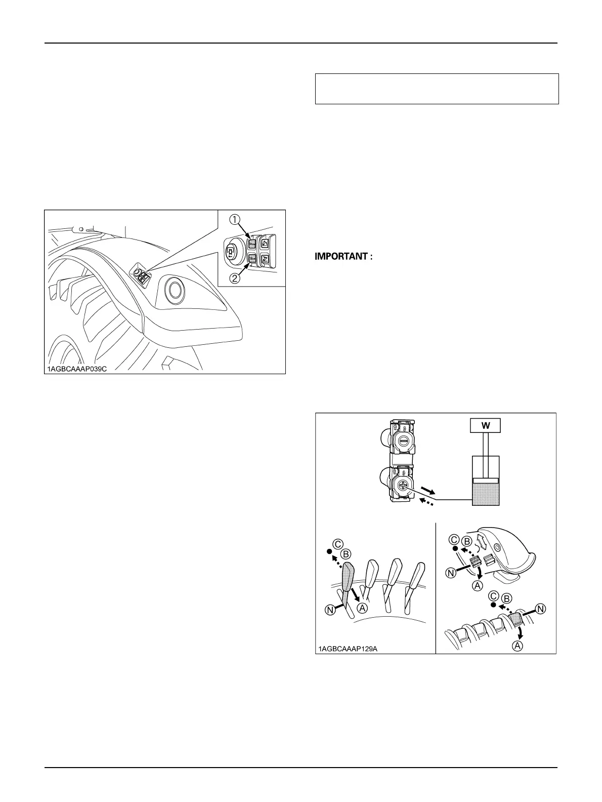
The left and right tire fenders are equipped with the 2nd-
segment remote control valve operation switch.
Before activating the switch, make sure that there is
nobody and no obstacle within the implement working
range.
The valve acts only while the switch is held down.
BOil Flow
C Connecting single-acting cylinder
1. Connect the hose to the lower coupler of the valve.
2. To extend a single-acting cylinder, move the control
lever or switch to extend (A) position.
Manually return the lever or switch to the neutral (N)
position to stop the cylinder when it has reached the
desired position.
To retract a single-acting cylinder, move the lever or
switch to float (C) position.
A Always use the float (C) position to lower a single
acting cylinder. The retract (B) position is for double
acting cylinders only.
A Do not hold the lever or switch in the extend (A)
position once the remote cylinder has reached the end
of the stroke, as this will cause oil to flow through the
relief valve. Forcing oil through the relief valve for
extended periods will overheat the oil.
A Hold the lever or switch at the float (C) position, and
the remote cylinder can be fully extended and
retracted. Select this float (C) position when you want
to run the implement along the terrain.
(1) Extend switch for 2nd remote control valve
(2) Retract switch for 2nd remote control valve
COMMON OPERATION OF
STANDARD/PREMIUM/PREMIUM KVT MODELS
(A) "EXTEND"
(B) "RETRACT"
(N) "NEUTRAL"
(C) "FLOAT"



 To Next Page