S-57
03-M-E3B, 03-M-DI-E3B, 03-M-E3BG WSM
DIESEL ENGINE
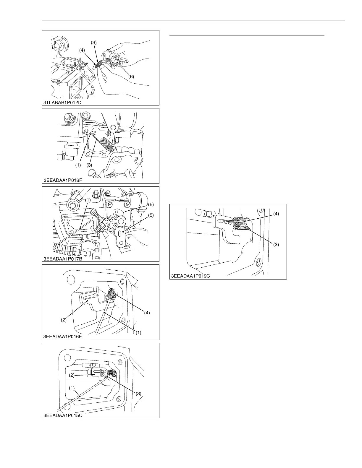
Governor Springs and Speed Control Plate (Continued)
(When reassembling)
• Hook the small spring (4) first and then the large governor spring
(3) on the speed control plate (6).
• Put the specific tool (1) from the injection pump side to catch the
large governor spring (3). Keep this spring slightly extended and
place the speed control plate (6) in its specified position.
• Using the specific tool (1), hook the small governor spring (4)
onto the fork lever (2).
NOTEQ
• Be careful not to stretch the small governor spring (4) too
long because otherwise it may get deformed permanently.
• Using the specific tool (1), hook the large governor spring (3)
onto the fork lever (2).
• Make sure both the governor springs (3), (4) are tight on the
fork lever (2).
• Apply and tighten up the two bolts and two nuts on the
speed control plate (6).
• Check that the speed control lever (5) positions low idle,
after assembling governor springs.
• Check that the speed control lever (5) returns to the high idle
position rather than the low idle position, after moving the
lever to the maximum speed position.
• Finally attach the injection pump cover in position.
W1152334
(1) Specific Tool
(2) Fork Lever
(3) Large Governor Spring
(4) Small Governor Spring
(5) Speed Control Lever
(6) Speed Control Plate
 Loading...