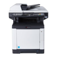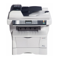
Do you have a question about the Kyocera FS-C2626MFP and is the answer not in the manual?
| Brand | Kyocera |
|---|---|
| Model | FS-C2626MFP |
| Category | All in One Printer |
| Language | English |
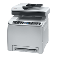
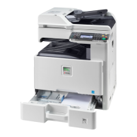
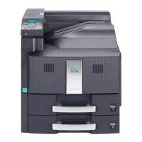
Official service manual for Kyocera FS-C2526MFP and FS-C2626MFP copiers.
Details about the manual's publication date and version.
Warning regarding the risk of explosion and proper disposal of batteries.
Records changes made across different revisions of the manual.
Overview of safety warnings and precautions for service personnel.
Explanation of symbols used for warnings, prohibitions, and required actions.
Essential warnings and cautions for safe and correct installation of the machine.
Critical safety warnings and cautions for performing maintenance procedures on the machine.
Guidelines for handling greases, solvents, and warnings about flammable materials.
Details on type, printing method, originals, paper weight, type, size, and speed.
Information on light source, scanning, CPU, memory, resolution, and operating environment.
Details on document processor and printer specs like speed, resolution, and OS support.
Details on scanner resolution, speed, and fax specifications for 4-in-1 models.
Diagram and labels identifying components on the front of the machine.
Diagram and labels identifying components on the rear of the machine.
Diagram and labels identifying components of the document processor.
Diagram and labels identifying the buttons and indicators on the operation panel.
Diagram illustrating the internal arrangement of major components within the machine.
Specifications for temperature, humidity, power supply, and location for machine installation.
Step-by-step guide for unpacking the machine and its accessories.
Instructions for removing protective tapes and pads before initial use.
Procedure for inserting toner containers and installing the waste toner box.
Guide on loading paper, connecting cables, and powering on the machine.
Procedure for installing optional expansion memory modules into the machine.
Procedure for installing an optional memory card into the interface slot.
Step-by-step process for selecting and running specific maintenance functions.
Comprehensive list of available maintenance items with their functions and initial settings.
Details on how to output status reports, event logs, and send data to USB memory.
Example output of event log and detailed causes for paper jam errors.
Procedures for restoring factory defaults and setting the machine serial number.
Initializing machine memory and correcting touch panel positions.
Checking DP operation and setting the type of IC card used by the machine.
Procedure to set, check, and clear the maintenance cycle and count.
Switching between single/double counts and selecting copy counting timing.
Determining service status page display and setting size conversion factors.
Setting maintenance due indication and performing automatic halftone adjustment.
Procedures for automatic adjustment of scanner and DP scanning sections.
Setting scan target values and adjusting scanning position and center line.
Initializing fax data, permanent data, and setting user data 1 and 2.
Configures lines ignored for fax reception and transmission system settings.
Manages communication speed, echo prevention, ECM, DIS signal, and V.34 settings.
Configures trailing edge margin detection, remote switching, and auto redialing.
Outputs fax transmission lists and customizes fax batch transmission and print size priority.
Individually sets software switches on the FAX control PWB for communication performance.
Lists maintenance kits and provides a gauge for repetitive defects.
Information on using FRPO commands to change printer parameters permanently.
Commands for adjusting print start timing, scanner magnification, and center line.
Adjusts DP scanning position, magnification, and timing for originals.
Overall wiring diagram illustrating connections between various PWBs and components.
Visual guide for installing the card reader holder and its components.
Contact details for KYOCERA Document Solutions in North and Latin America.
Contact details for KYOCERA Document Solutions in Europe, Asia, and other regions.
Description of the cassette paper feed mechanism, including rollers and sensors.
Description of the MP tray paper feed mechanism, rollers, sensors, and separation pad.
Description of the path that conveys paper to transfer/separation and registration rollers.
Description of the drum, charger roller unit, and cleaning unit components.
Description of the developing unit, including sleeve roller, magnet roller, and toner sensor.
Description of the LED illumination, CCD sensor, mirrors, and ISU lens for scanning.
Description of the laser beam scanning process using polygon motor and lenses.
Description of the transfer belt, rollers, cleaning units, and ID sensors.
Description of the secondary transfer roller, separation brush, and bias application.
Description of the fuser section, including heat roller, press roller, and thermistor.
Description of the path for ejecting paper to the inner tray or duplex section.
Description of the path for conveying paper during duplex printing.
Description of components for feeding originals onto the table and conveying section.
Description of the path for conveying originals through the DP contact glass.
Description of components for ejecting originals and switchback scanning.
Identification and function of major PWBs like Main, Engine, Power Source, and High Voltage.
Diagram and list of switches and sensors with their functions.
Diagram and list of motors and their roles in driving various machine sections.
Identification and functions of clutches, solenoids, and cleaning lamps.
Identification of DP drive PWB, sensors, motors, solenoids, and clutches.
Diagram showing connector locations on the Power Source PWB.
Details of pins, signals, voltage, and description for YC101, YC102, YC103, YC104, YC105.
Diagram showing component and connector locations on the Engine PWB.
Pin details for connectors YC3, YC4, YC6, YC7, YC8, YC9, YC10, YC11, YC12, YC13, YC14, YC15, YC16, YC17, YC18, YC19, YC20, YC21, YC23, YC24.
Diagram showing component and connector locations on the Main PWB.
Pin details for connectors YC8, YC16, YC32, YC34, YC35, YC36, YC37, YC38, YC39, YC40, YC41, YC42, YC100, YC101, YC107, YC108, YC109.
Diagram showing connector locations on the Drum relay PWBs (YC1-YC9).
Pin details for connectors YC1, YC2, YC3, YC4, YC5, YC6, YC7, YC10, YC13.
Diagram showing connector locations on the DP Drive PWBs (YC1-YC8).
Pin details for connectors YC1, YC2, YC3, YC4, YC5, YC6, YC8.
Lists of maintenance kits, their part numbers, and alternative part numbers.
Diagram showing measurement points for repetitive defects related to rollers and drum.
Information on using FRPO commands to change printer parameters permanently.
Commands for adjusting print start timing, scanner magnification, and center line.
Adjusts DP scanning position, magnification, and timing for originals.
Overall wiring diagram illustrating connections between various PWBs and components.
Visual guide for installing the card reader holder and its components.