Do you have a question about the Kyocera FS-C5150DN and is the answer not in the manual?
Explains warning symbols for danger, caution, and prohibited/required actions.
Details technical specifications like type, printing method, paper weight, size, speed.
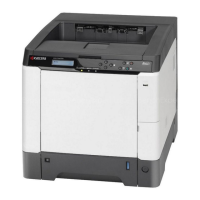
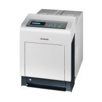
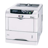
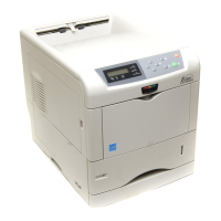
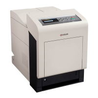
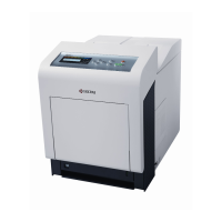
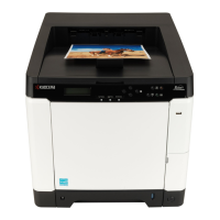
Identifies and labels various parts of the machine from front and rear views.
Illustrates the internal mechanical layout and component arrangement.
Specifies required conditions for temperature, humidity, power, and location.
Provides step-by-step instructions for safely removing the machine from its packaging.
Guides on how to install optional memory modules into the machine.
Instructions for installing an optional hard disk drive.
Details the process for installing an optional network interface card.
Explains how to enter and execute various service modes for maintenance.
Details functions like printing status pages for service purposes.
Guides on identifying and resolving paper jam issues.
Explains the machine's self-diagnostic capabilities and error codes.
Lists common image quality issues and their causes/solutions.
Troubleshoots issues related to the machine's electrical components and power.
Addresses problems arising from mechanical failures or misalignments.
Outlines essential safety measures and handling guidelines before disassembly.
Details procedures for removing and refitting various external covers of the machine.
Explains how to detach and reattach paper feed components like rollers.
Guides on removing and reinstalling the developing units for toner application.
Details the process for detaching and refitting the drum units.
Explains how to remove and reinstall transfer belt and roller components.
Provides instructions for detaching and refitting the fuser unit.
Covers the procedure for detaching and refitting main Printed Wiring Boards (PWBs).
Details the removal and installation of drive units for various machine functions.
Explains how to detach and refit the laser scanner unit.
Covers removal and installation of other components like paper conveying and operation panels.
Provides steps to update the machine's firmware via USB.
Notes regarding EEPROM transfer during engine PWB replacement.
Describes the mechanical construction of paper feeding and conveying systems.
Details the components and function of the drum section.
Explains the construction and operation of the developing unit.
Describes the laser scanner assembly and its function.
Covers the intermediate transfer unit and secondary transfer roller.
Details the components and operation of the fuser unit.
Describes the paper path for ejecting and feed shifting.
Explains the paper path for duplex printing.
Lists and describes the various Printed Wiring Boards (PWBs) in the machine.
Identifies and describes the function of all switches and sensors.
Lists and describes the function of all motors within the machine.
Identifies and describes other electrical components like clutches and heaters.
Details the connectors and functions of the power source PWB.
Shows the silk-screen layout and component placement of the engine PWB.
Displays the silk-screen diagram and component layout of the main PWB.
Shows the silk-screen diagram for the drum relay PWB.
Includes supplementary information like maintenance kits and firmware commands.
Provides a tool to measure and identify repeating print defects.
Explains how to use FRPO commands for firmware settings.
Illustrates the electrical connections and signal paths within the machine.