2JL/2JJ/2JG/2JD
2-1-9
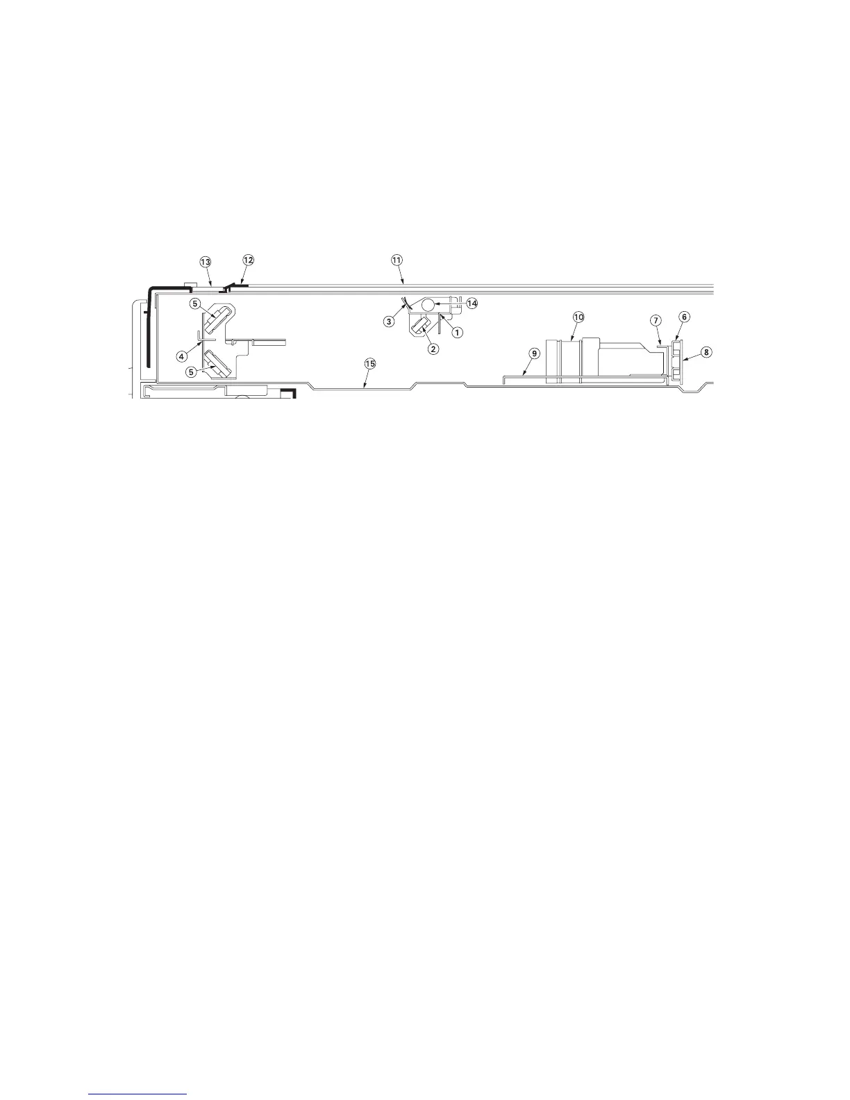
2-1-4 Optical section
The optical section consists of the scanner, mirror frame and image scanner section for scanning and the laser scanner
unit for printing.
(1) Image scanner section
The original image is illuminated by the exposure lamp (EL) and scanned by the CCD in the CCD PWB (CCDPWB) via the
three mirrors and lens, the reflected light being converted to an electrical signal. The mirror frame A and B travel to scan
on the optical rails on the front and rear of the machine to scan from side to side. The speed of the mirror frame B is half
the speed of the mirror frame A.
Figure 2-1-11 Image scanner section
(1) Mirror frame A
(2) Mirror A
(3) Scanner reflector
(4) Mirror frame B
(5) Mirror B
(6) CCD mount
(7) CCD adjusting plate
(8) CCD PWB (CCDPWB)
(9) Lens mount
(10) ISU lens
(11) Contact glass
(12) Original size indicator plate
(13) Slit glass
(14) Exposure lamp (EL)
(15) Scanner frame
 Loading...