2JL/2JJ/2JG/2JD-2
1-2-12
1-2-3 Installing the key counter (option)
Key counter installation requires the following parts:
Key counter (P/N 82142540)
Key counter set (P/N 302A369708)
Key counter mount (P/N 302FZ03010)
One (1) M4 × 8 tap-tight S screw (P/N B1A54080)
Supplied parts of key counter set:
Key counter socket assembly (P/N 3029236241)
Key counter cover (P/N 3066060011)
Key counter mount (P/N 3066060041)
Key counter retainer (P/N 302GR03020)
Key counter cover retainer (P/N 302GR03010)
One (1) M3 × 8 tap-tight P screw (P/N 5MBTPB3008PW++R)
Two (2) M4 × 10 tap-tight P screws (P/N 5MBTPB4010PW++R)
Two (2) M4 × 10 tap-tight S screws (P/N 5MBTPB4010TW++R)
Two (2) M3 × 6 bronze flat-head screws (P/N 7BB003306H)
One (1) M4 × 20 tap-tight S screw (P/N 7BB100420H)
One (1) M3 bronze nut (P/N 7BC1003055++H01)
One (1) M3 × 8 bronze binding screw (P/N B1B03080)
One (1) M4 × 30 tap-tight S screw (P/N B1B54300)
Four (4) M4 × 6 chrome TP screws (P/N B4A04060)
Two (2) M4 × 10 chrome TP screws (P/N B4A04100)
Procedure
1. Turn the main power switch off and discon-
nect the power cord plug from the AC outlet.
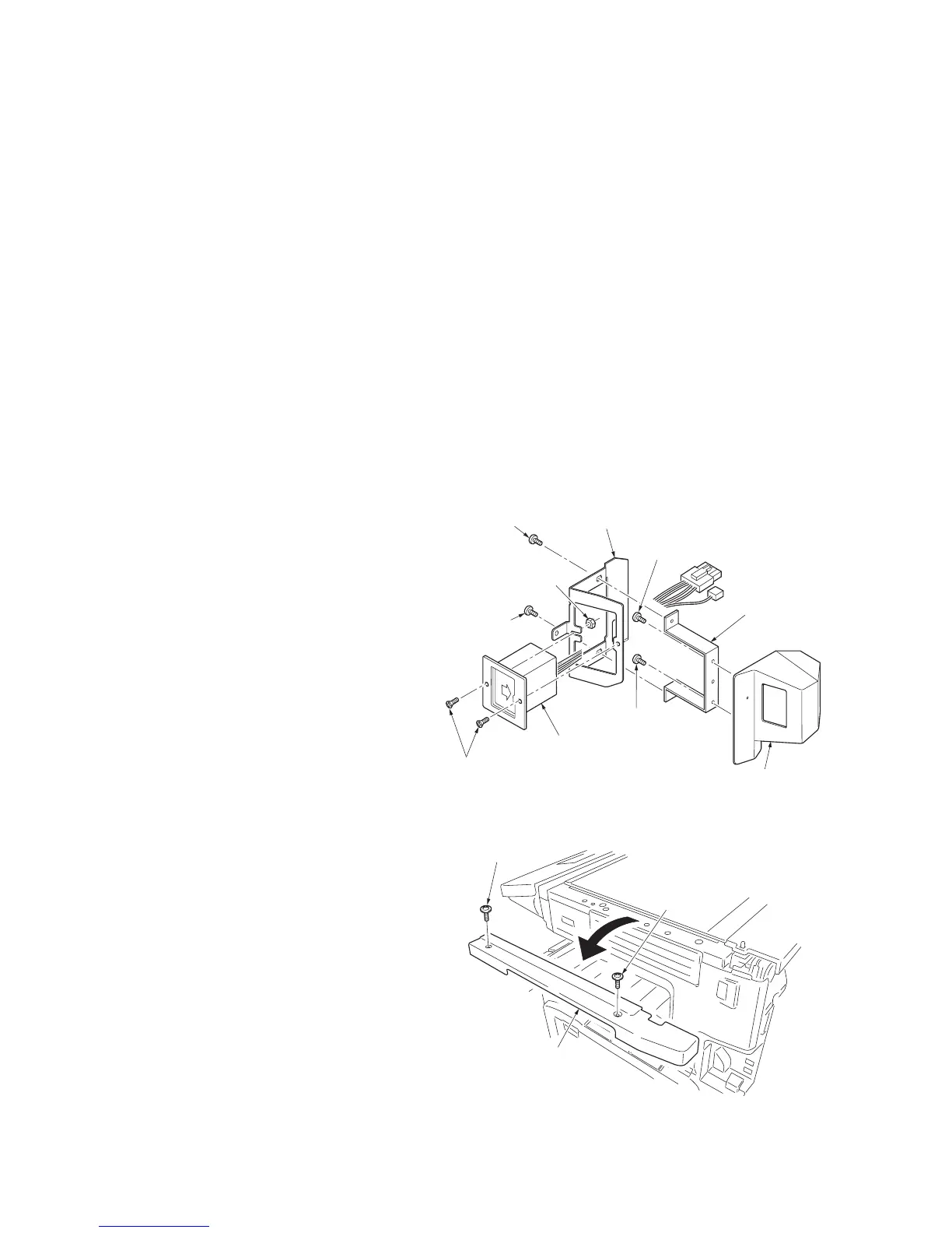
2. Fit the key counter socket assembly to the
key counter retainer using the two screws
and nut.
3. Fit the key counter mount to the key counter
cover using the two screws, and attach the
key counter retainer to the mount using the
two screws.
Figure 1-2-15
4. Remove the two screws and then remove
the scanner right cover.
Figure 1-2-16
M3 x 6 flat-head
screws
(7BB003306H)
Key counter
mount
(3066060041)
Key counter cover
(306606001)
M4 x 6 screw
(B4A04060)
M4 x 6 screw
(B4A04060)
Key counter
socket assembly
(3029236241)
M4 x 6 screw
(B4A04060)
M3 nut
(7BC1003055++H01)
Key counter retainer
(302GR03020)
M4 x 6 screw
(B4A04060)
Scanner right cover
Screw
Screw
 Loading...