L-ACOUSTICS V-DOSC Manual Version 4 6/29/2005 Page 112 of 158
4.2 FLOWN SYSTEM
Rigging a V-DOSC array is fast and easy, with significantly reduced handling time compared to
conventional systems. Please refer to the photo sequence in Figure 94 with respect to the following
description of flying procedures.
Preliminary Preparations
All installation data for rigging the array (i.e., bottom enclosure elevation, inter-enclosure angles,
top and bottom enclosure site angles) has been calculated using ARRAY 2004 or SOUNDVISION
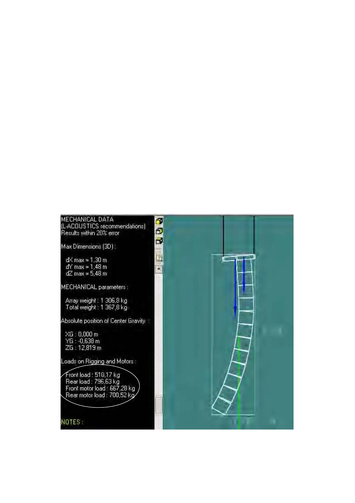
and mechanical data checked to ensure safe rigging conditions (see Figs 92-94).
Two independent rigging points are available with a spacing of 1.05 meters (43 ¼”) and the
desired onstage rotation angle for the array. Alternatively, three points can be used along with a
swivel shackle for connecting the delta plate to the rear BUMP2 point – this allows for pan
adjustment of the flown array (see Fig. 19).
Rigging points should be equipped with 0.5T chain motors for a 4-enclosure array, 1.0T motors
for a 5- to 10-enclosure array, 2.0T motors for an 11- to 16-enclosure array.
Access is available beneath the rigging points, i.e., a flat surface where it is possible to roll V-
DOSC enclosures into position – preferably from behind the installation location but it is also
possible to fly the system with enclosures lined up perpendicular to the rigging points (eg. from
the floor along the front of a stage).
Figure 92: SOUNDVISION mechanical data
FRONT
LOAD
(angle straps)
REAR
LOAD
(rotating legs)
FRONT
MOTOR
REAR
MOTO