Home
L-Acoustics
Amplifier
V-DOSC
L-Acoustics V-DOSC User Manual
4
of 1
of 1 rating
158 pages
Give review
Manual
Specs
To Next Page
To Next Page
To Previous Page
To Previous Page
Loading...
L-ACOUSTICS V-DOSC Manual Ve
rsion 4
6/29/2005
Page 98 of 158
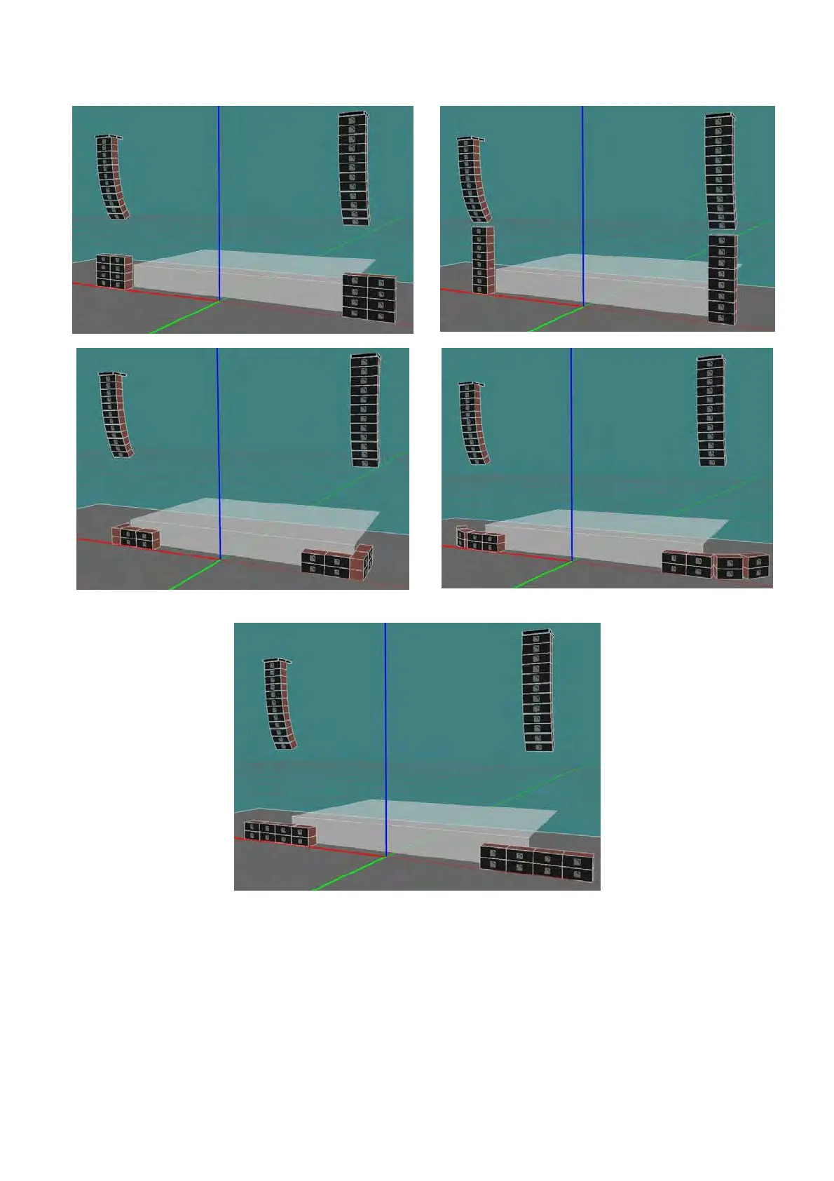
(a) L/R subwoofer array blocks
(b) L/R column line arrays
(c) L-Wrap L/R subwoofer arrays
(d) Curved L/R subwoofer arrays
(e) L/R horizontal line arrays
Figure 75: L/R Subwoofer arraying techniques
97
99
Table of Contents
Table of Contents
5
List of Figures
8
List of Tables
10
Introduction
11
Wavefront Sculpture Technology Fundamentals
11
The Sound Reinforcement Problem
11
Wavefront Sculpture Technology Background
12
Figure 1: Wavefront Interference Versus a Sculptured V-DOSC Wavefront
12
Figure 2: Wavefront Sculpture Technology Conditions 1 and 2 Illustrated
13
V-Dosc: the Solution
14
Figure 3: Coplanar Symmetry of V-DOSC
15
Figure 4: Cylindrical Versus Spherical Wave Propagation
16
Figure 5: V-DOSC Array
17
V-Dosc Training and Qualifications
18
Qualified V-Dosc Technician (Qvt)
18
Certified V-Dosc Engineer (Cve)
18
The V-Dosc System Standard
19
Figure 6: V-DOSC System Block Diagram
20
Figure 7: LR System Configuration
21
Figure 8: LR System Plus Offstage Fill Configuration
22
V-Dosc System Components
23
Loudspeaker Enclosures
23
Figure 9: V-DOSC System Loudspeakers Plus Accessories
23
Rigging Accessories
24
Figure 10: V-DOSC Rigging Accessories
25
Subwoofer Enclosures
26
Subwoofer Rigging Accessories
26
Figure 11: V-DOSC Subwoofer Options
26
Figure 12: Subwoofer Rigging Accessories
26
Amplification
27
Amplifier Racks
27
Figure 13: L-ACOUSTICS La48A Power Amplifier
27
Figure 14: Amplifier Rack Options and Accessories
28
Signal Distribution and Cabling
29
Figure 15: Signal Distribution and Cabling
30
Loudspeaker Cabling
31
Figure 16: Loudspeaker Cabling Options
32
Figure 17: V-DOSC Enclosure - Front and Rear Views
33
V-Dosc Specifications
33
Figure 18: V-DOSC BUMP2
34
V-Dosc Rigging System
34
Figure 19: BUMPDELTA
35
Sb218 Subwoofer Specifications
35
Figure 20: SB218 Subwoofer - Front and Rear Views
36
Figure 21: BUMPSUB SB218 Flying Bar
37
Sb218 Rigging System
37
Powering V-Dosc
38
Table 1: L-ACOUSTICS La48A Power Amplifier Ratings
38
Table 2: Load and Power Ratings for V-DOSC
39
Figure 22: V-DOSC Pado4A Amplifier Rack Panel
40
Figure 23: V-DOSC Pado2A Amplifier Rack Panel
40
V-Dosc Amp Panels
40
Figure 24: Pado4A Amp Rack Wiring
41
Table 3: Pado4A COMB Wiring Chart
41
Table 4: Pado4A Internal Amp Rack Wiring Chart
41
Figure 25: Pado2A Amp Rack Wiring
42
Table 5: Pado2A COMB Wiring Chart
42
Table 6: Pado2A Internal Amp Rack Wiring Chart
42
Figure 26: L-ACOUSTICS Amplifier Rack Rk124A Loaded with 4 X L-ACOUSTICS La48A Amplifiers
43
V-DOSC AMPLIFIER Racks
43
Figure 27: L-ACOUSTICS Amplifier Rack Options
44
Comb Connectors
45
Table 7: V-DOSC Preset DSP Output Channel Assignment and COMB Connector Summary
45
Figure 28: L-ACOUSTICS Rk122A Amplifier Rack Channel Assignments and Cabling
46
Figure 29: L-ACOUSTICS Rk124A Amplifier Rack Channel Assignments and Cabling
46
Figure 30: L-ACOUSTICS Rk122A Amp Rack Channel Assignments for 2-Way, 3-Way Stereo Presets
47
Table 8: 2-Way, 3-Way Stereo Preset DSP Output Channel Assignment and COMB Connector Summary
47
Figure 31: L-ACOUSTICS Rk124A Amp Rack Channel Assignments for 2-Way, 3-Way Stereo Presets
48
Co24 Control Output Panel
49
Figure 32: CO24 Control Output Panel
49
Co6 Control Output Panel
50
Figure 33: MD24 Multi Distro Panel
50
Figure 34: CO6 Control Output Panel
50
Md24 Multi Distro Panel
50
Approved Digital Signal Processors
51
Oem Factory Presets
51
V-Dosc Presets
52
Table 9: SUB / LOW OPERATING BANDWIDTH SUMMARY
52
3-Way Stereo Presets
53
3Wx Preset
53
Infra Preset
53
Figure 35: Spectral Balance for SUB/LOW Versus MID/HI Sections
53
Figure 36: Spectral Balance for SUB/LOW Versus MID/HI Sections (V6 Presets and Earlier)
53
Lo/Hi Presets
53
4-Way Presets
54
Subwoofer Time Alignment Recommendations
54
Sub/Low Gain Scaling Procedures
54
Subwoofer Presets (Delay Arc, Lcr)
54
Infra Preset
55
Preset
55
Figure 37: Infra Preset Time Alignment Procedure
55
Figure 38: 4W Preset Time Alignment Procedure
55
Preset
56
Aux Preset
56
Figure 39: X Preset Time Alignment Procedure
56
Figure 40: X AUX Preset Time Alignment Procedure
56
5-Way Presets
57
Infra Preset
57
X Preset
57
Figure 41: 5W Infra Preset Time Alignment Procedure
57
Figure 42: 5W X Preset Time Alignment Procedure
57
General Guidelines Regarding System Protection
58
Table 10: Recommended Limiter Threshold Settings
58
Table 11: XTA DP224 Presets
59
Xta Dp224 V-Dosc Presets
59
Table 12: XTA DP226 Presets
60
Xta Dp226 V-Dosc Presets
60
Lake Contour V-Dosc Presets
61
Table 13: Lake Contour Presets
61
Bss Fds 366 V-Dosc Presets
62
Table 14: BSS FDS 366 Presets
62
V-Dosc Coverage Modeling
63
Coverage in the Horizontal Plane
63
Figure 43A: Horizontal V-DOSC Isocontour Averaged from 630 Hz - 16 Khz
63
Figure 43B: Horizontal V-DOSC Isocontour Averaged from 32 Hz - 630 Hz
63
Coverage in the Vertical Plane
64
Flat V-DOSC Array
64
Curved V-DOSC Array
64
Constant Curvature V-DOSC Array
65
Figure 44: Constant Curvature Array Examples
65
Variable Curvature V-DOSC Array
66
V-Dosc Coverage Modeling Using Array 2004
66
Cutview Sheets
67
V-ARRAY1, V-ARRAY2 Input Data
67
Figure 45: Defining Cutview Dimensions
67
Figure 46: Parameters for the ROOM DIM Utility Sheet in ARRAY
68
Optimization Procedure
69
Figure 47 (A): Cutview Showing Non-Constant Enclosure Site Angle Impact Spacing
69
Figure 47 (B): Cutview Showing Constant Enclosure Site Angle Impact Spacing
69
Figure 47 (C): Plan View Representation of Non-Constant (A) Versus Constant Spacing (B) Arrays
69
Output Data
70
Figure 48: ARRAY 2004 Geometric Data for V-DOSC
71
DV-ARRAY1, DV-ARRAY2 Input Data
72
DV-DOSC PICK POINT UTILITY
72
Figure 49: ARRAY 2004 Geometric Data for DV-DOSC
73
H-Isocont Sheet
74
Input Data
74
Optimization Procedure
74
Output Data
74
Figure 50: ARRAY 2004 Spreadsheet Calculation Example
75
V-Dosc Coverage Modeling Using Soundvision
76
Figure 51: SOUNDVISION Geometric Data for V-DOSC
77
Figure 52: Plan View SPL Mappings at Octave Band Frequencies for 12 V-DOSC
78
Figure 53: Impact Coverage and SPL Mappings for 12 V-DOSC
79
Figure 54A: Stadium Example - Rear Perspective View of Full System Impact Coverage
80
Figure 54B: Stadium Example - Plan View of Full System Impact Coverage
80
Soundvision Examples
80
Soundvision Stadium Example
80
Figure 55: Stadium Example - Rear Perspective View of 1-10 Khz SPL Mappings
81
Figure 56: Arena Example -Rigging Plot
82
Figure 57: Arena Example - Plan View of Full System Impact Coverage
82
Soundvision Arena Example
82
Figure 58: Arena Example - Rear Perspective View of Full System Impact Coverage
83
Figure 59A: Arena Example - Rear Perspective View of Full System SPL Map (1-10 Khz)
83
Figure 59B: Arena Example - Plan View of 1-10 Khz SPL Mappings
84
Sound Design
85
Stacked or Flown
85
Stacking Guidelines
86
Figure 60: Illustration of Stacking Guidelines
86
Figure 61: Stacked System Example
86
Flying Guidelines
87
Figure 62: Illustration of Flying Guidelines
87
Figure 63: Flown V-DOSC System
87
Achieving Optimum Coverage
88
The Left/Right Configuration
88
Tradeoffs between Intelligibility and Stereo Imaging
88
LEFT/CENTRE/RIGHT (LCR) Configurations
89
Figure 64: Tradeoffs between Intelligibility Versus Stereo Imaging
89
Figure 65: LCR Configurations
89
Multiple Array Concepts
90
Figure 66: Generic Rigging Plot for a V-DOSC System with Main L/R FOH and LL/RR Offstage Fill Arrays
90
Figure 67: Rigging Plot for a L/R V-DOSC + Flown SB218 System with LL/RR DV-DOSC Offstage Fill
91
Figure 68: Stereo DV-DOSC Offstage Fill System
91
Subwoofers
92
Flown V-DOSC and Ground Stacked Subwoofers
93
Figure 69: Flown V-DOSC and Ground Stacked Subwoofer Configurations
93
Figure 70: Flown V-DOSC and Ground Stacked Subwoofer Time Alignment
93
Figure 71: Time Alignment Location for Flown V-DOSC, Ground Stacked L/R Subwoofers
94
Physically Coupled Subwoofers
95
Figure 72: Physically Coupled Subwoofer Configurations
95
Hybrid Flown/Stacked Subwoofers
96
Figure 73: Hybrid Flown/Stacked Subwoofer Configurations
96
Figure 74: Hybrid Flown/Stacked Subwoofer Example
96
Subwoofer Arraying Techniques
97
Left/Right Configurations
97
Figure 75: L/R Subwoofer Arraying Techniques
98
Central Line Array with Electronic Delay Processing
99
Figure 76: Centre Subwoofer Line Array (A) Without and (B) with Electronic Delay Processing
99
Left/Centre/Right Configurations
100
Figure 77: Electronic Delay Processing Examples Using a 4- or 6-Channel DSP
100
Figure 78: LCR Subwoofer Arraying Techniques
101
Large Format Subwoofer Array Configurations
102
Figure 79: Large Format Subwoofer Configuration with Electronic Delay Processing
102
Figure 80: Geometric Coordinates for the SUB ARC Utility Spreadsheet in ARRAY2004
103
Figure 81: Large Format Arena Configuration - 4 Delay Taps
103
Figure 82: Large Format Open Air Festival Configuration
104
Figure 83: Large Format Stadium Configuration
104
Complementary Fill Systems
105
Front Fill
105
Figure 84: Stereo Infill and Distributed Front Fill Options
105
Offstage Fill
106
Figure 85: Flown Offstage Fill System Options
106
Figure 86: Stacked Offstage Fill System Options
106
Delay Systems
107
Figure 87: SOUNDVISION Simulation for a LL/L/R/RR V-DOSC FOH System with 4 Delay Positions
107
Figure 88: Flown and Stacked Delay Systems
108
Figure 89: Stacked DV-DOSC Delay System
108
Figure 90: Flown V-DOSC Delay System
108
Installation Procedures
109
Stacked System
109
Table 15: Angle Strap Values
110
Figure 91: Stacked V-DOSC Offstage Fill System
111
Flown System
112
Figure 92: SOUNDVISION Mechanical Data
112
Figure 93: SOUNDVISION Installation Report Data
113
Figure 94: ARRAY 2004 Installation Data
113
Figure 95: Photo Sequence Showing the Steps Involved in Flying V-DOSC
119
V-Dosc System Operation
123
System Tonal Balance
123
Measurement Procedures
125
Measurement Instruments
125
Measurement Tips
126
Step-By-Step Tuning Procedure
127
Maintenance and Installation Tools
129
Recommended Maintenance Procedures
129
Recommended Maintenance Tools
129
Spare Parts
130
Recommended Installation Tools
131
Figure 96: Recommended Installation Tools
131
Specifications
132
V-Dosc Enclosure Specifications
132
Figure 97: V-DOSC Enclosure - Line Drawing
133
Sb218 Subwoofer Specifications
134
Figure 98: SB218 Subwoofer - Line Drawing
134
Rigging Structures
135
V-DOSC BUMP2 Bumper
135
Figure 99: V-DOSC Flying Bumper - Line Drawing
135
SB218 BUMPSUB Rigging Bar
136
Figure 100: SB218 Flying Bar - Line Drawing
136
Table 16: Weights for Flown V-DOSC System
136
CO24, MD24 Line Assignment Summary
137
Table 17: Whirlwind W6 MASS Connector Input/Output Line Assignments
137
CO24 Control Output Panel Line Assignments
138
Table 18A: CO24 W6 Pin Assignments
138
Table 18B: CO24 W6 Socket Assignments
139
MD24 Multi Distro Panel Line Assignments
140
Table 19A: MD24 W6 Pin Assignments
140
Table 19B: MD24 W6 Socket Assignments
141
APPENDIX 1: Why Do Separated Sound Sources Interfere
142
Figure 101: the Interference Problem
142
Figure 102: Comb Filtering Due to Path Length Differences between Sources
143
APPENDIX 2: Further Explanations Regarding WST Criteria
144
Figure 103: Destructive Interference Ring for a Line Array at Observation Point M
144
Figure 104: the Effect of Varying Frequency and Listener Position M on Fresnel Rings
145
Figure 105: Destructive and Constructive Interference Rings for a Line Array at Observation Point M
145
Figure 106: Constructive Interference Rings for a Condensed Point Source Line Array
146
Figure 107: Destructive Interference Rings out of Beamwidth for Condensed and Standard Line Arrays
147
Figure 108: Front View of V-DOSC Array and Vertically Stacked DOSC Waveguides
148
APPENDIX 3: How Does V-DOSC Behave with Respect to WST Criteria
148
Figure 109: Horn Generated Wavefronts
149
Figure 110: DOSC Waveguide - Internal Section
149
APPENDIX 4: How Does the DOSC Waveguide Work
149
Figure 111: Illustration of the Fresnel and Fraunhofer Regions
150
APPENDIX 5: the Border between Fresnel and Fraunhofer Regions
150
Figure 112: Illustration of Dborder and DV for a Flat 12 Enclosure Array
151
Table 20: Border (in M) between Cylindrical (Fresnel) and Spherical (Fraunhofer) Zones
151
Table 21: DV - Vertical Coverage Angle in the Farfield Region
151
Figure 113: Illustration of the Variation of Vertical Coverage Angle with Frequency
152
APPENDIX 6: Pattern Control of a Constant Curvature Array
152
Table 22: WST Criteria Number 5
153
APPENDIX 7: WST Criteria Number 5
153
Figure 114: Angle Strap Calibration
154
APPENDIX 8: Angle Strap Calibration
154
APPENDIX 9: V-DOSC Rigging Certification
155
4
Based on 1 rating
Ask a question
Give review
Questions and Answers:
Need help?
Do you have a question about the L-Acoustics V-DOSC and is the answer not in the manual?
Ask a question
L-Acoustics V-DOSC Specifications
General
Brand
L-Acoustics
Model
V-DOSC
Category
Amplifier
Language
English
Related product manuals
L-Acoustics LA4
94 pages
L-Acoustics LA48A
24 pages
L-Acoustics LA 24
25 pages
L-Acoustics LA24a
23 pages