ESI-2000
Pilot’s Guide 3-9
Operating Instructions
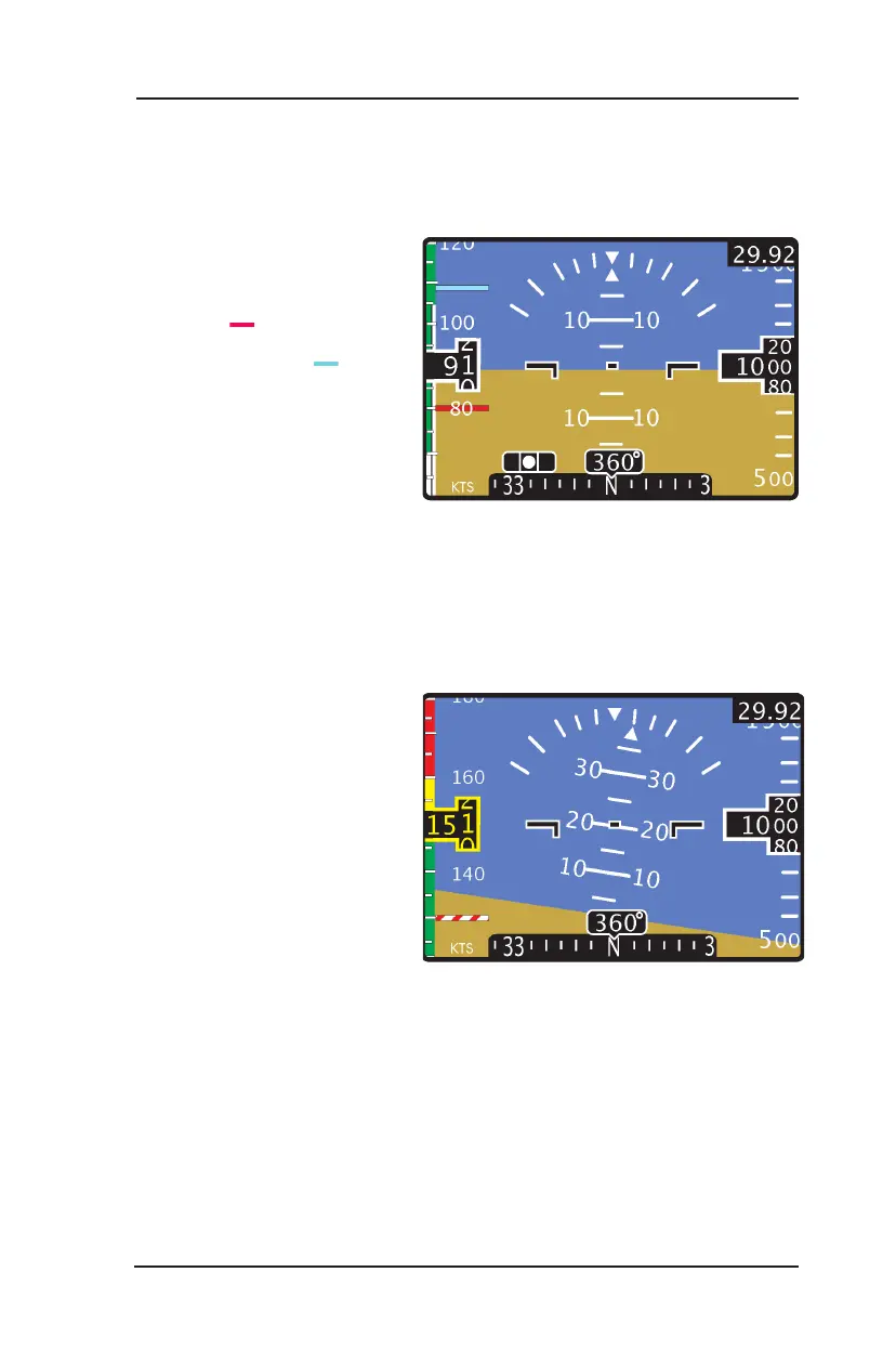
Figure 3-11 depicts a display congured to show twin-engine airspeed set
points, V
yse
and V
mc
(Part 23/25 aircraft) .The display is shown ascending
with the airspeed awareness
bar showing best rate of
climb (V
yse
) and minimum
control speed (V
mc
) with
critical engine inoperative.
Figure 3-11: Display Showing Vmc & Vyse
Figure 3-12
depicts a display congured to show Part 27/29 Rotorcraft.
The display is shown ascending while banking to the left. The Airspeed
awareness bar is showing
V
NE
Power On set to 160, V
NE
Power Off set to 130 (see red/
white horizontal bar), and the
start of the caution range for
airspeed warning (V
CAUTION
)
set to 150.
Figure 3-12: Display Showing Airspeed with Part 27/29
IN-FLIGHT SCREEN EXAMPLES (Continued)