EasyManua.ls Logo

L3 comminications Trilogy ESI-2000 User Manual

L3 comminications Trilogy ESI-2000
64 pages
To Next Page IconTo Next Page
Page #1 background imageLoading...
Page #1 background image
Pilot’s Guide
for the
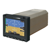
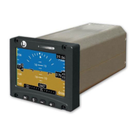
Electronic Standby Indicator
Avionics Systems
Model ESI-2000
Software Release 1.x

Table of Contents

Questions and Answers:

L3 comminications Trilogy ESI-2000 Specifications

General IconGeneral
BrandL3 comminications
ModelTrilogy ESI-2000
CategoryTouch Panel
LanguageEnglish

Summary

Chapter 1 Description

Introduction

Overview of the ESI-2000 Electronic Standby Indicator.

Software Release

Details on available software versions for the ESI-2000.

Specifications

Technical specifications including physical, power, environmental, and certification.

Optional Equipment

Information on optional accessories like magnetometers (MAG-3100, MAG-3000).

Limitations

Operational constraints for heading reference in polar regions due to magnetic field.

Display Elements

Detailed description of all visual elements displayed on the ESI-2000 screen.

Battery

Explains battery indicators, charging, and availability status for the unit.

Chapter 2 Basic Operation

Introduction

Introduces the user interface and navigation of the ESI-2000 indicator.

Menu Operation

Guide to navigating and selecting options within the ESI-2000 menu system.

Brightness Adjustment

Instructions for adjusting the display brightness level using menu options.

User Initiated Alignment

Procedure for re-aligning the attitude and heading reference of the indicator.

Baro Units Adjustment

How to change the barometric unit selection (in. Hg, hPa, mb) in the menu.

Baro Adjustment

Steps to adjust the barometric pressure value displayed on the unit.

Status Screen

Viewing system status, serial number, operating hours, and battery information.

Battery Capacity Meter Calibration Procedure

Annual procedure to maintain accuracy of the battery capacity meter.

Chapter 3 Operating Instructions

Introduction

Describes the operation of the ESI-2000 indicator.

Power On

Details the startup sequence and indicators when applying power to the unit.

Cycle Power Instructions

Procedure for cycling power to the ESI-2000 for reset or troubleshooting.

Power Off

Instructions for shutting down the ESI-2000 to conserve battery energy.

System Identification

Information displayed during the system identification splash screen.

Alignment

Process for aligning the indicator's attitude and heading data.

Normal Operation

Overview of the display elements during normal flight operations.

Pre-Flight Instructions

Recommended checks and settings before taking off with the ESI-2000.

In-Flight Instructions

Actions the pilot may need to perform while the aircraft is in flight.

In-Flight Screen Examples

Visual examples of various display configurations during flight.

Errors and Invalidities

Guidance on identifying and understanding error messages and invalid data displays.

Chapter 4 Troubleshooting

Corrective Actions

Table of common conditions, their causes, and corrective actions for the ESI-2000.

Attitude or heading does not match primary flight display

Corrective steps when attitude or heading data is inconsistent with primary flight instruments.

"Attitude Fail" replaces Attitude

Troubleshooting steps when the "Attitude Fail" message appears on the display.

Airspeed Awareness Color Band removed and SPD message displayed

Steps to address loss of airspeed configuration data indicated by a missing color band.

Blank display

Troubleshooting steps for a blank screen, potentially due to low brightness.

"BATT WORN OUT... REPLACE” message is displayed on screen during startup

Action to take when the battery is no longer holding a charge.

Battery Failed Indicator

Troubleshooting for the red battery failed indicator, indicating system failure.

Battery not available

Steps to resolve when the battery is unavailable due to temperature or voltage issues.

Red X in place of Altitude OR Red X in place of Airspeed

Troubleshooting steps for loss of altitude or airspeed data indicated by a red X.

Appendix A

Record Of Important Information

Section to log important dealer, equipment, and aircraft information.

Dealer Information

Fields for recording dealer contact and identification details.

Equipment Information

Fields for recording purchase date, model, part, and serial numbers.

Aircraft Information

Fields for recording aircraft make, model, and registration number.

Installation Notes

OPTIONS

Installer to complete configuration options for tape type, baro color, and units.

AIRSPEED

Installer to record airspeed settings for different aircraft types and configurations.

ANGLES

Installer to record panel angles (pitch, roll, yaw) during initial installation.

MAG INSTALL

Installer to record magnetic installation details, including mounting and compensation.

Related product manuals