Chapter 6 - Removing & Replacing the Desiccant Assembly TM00358 Rev. A
October 2007 L-3 WESCAM
108 All Rights Reserved
6.5 REMOVING & REPLACING THE DESICCANT ASSEMBLY
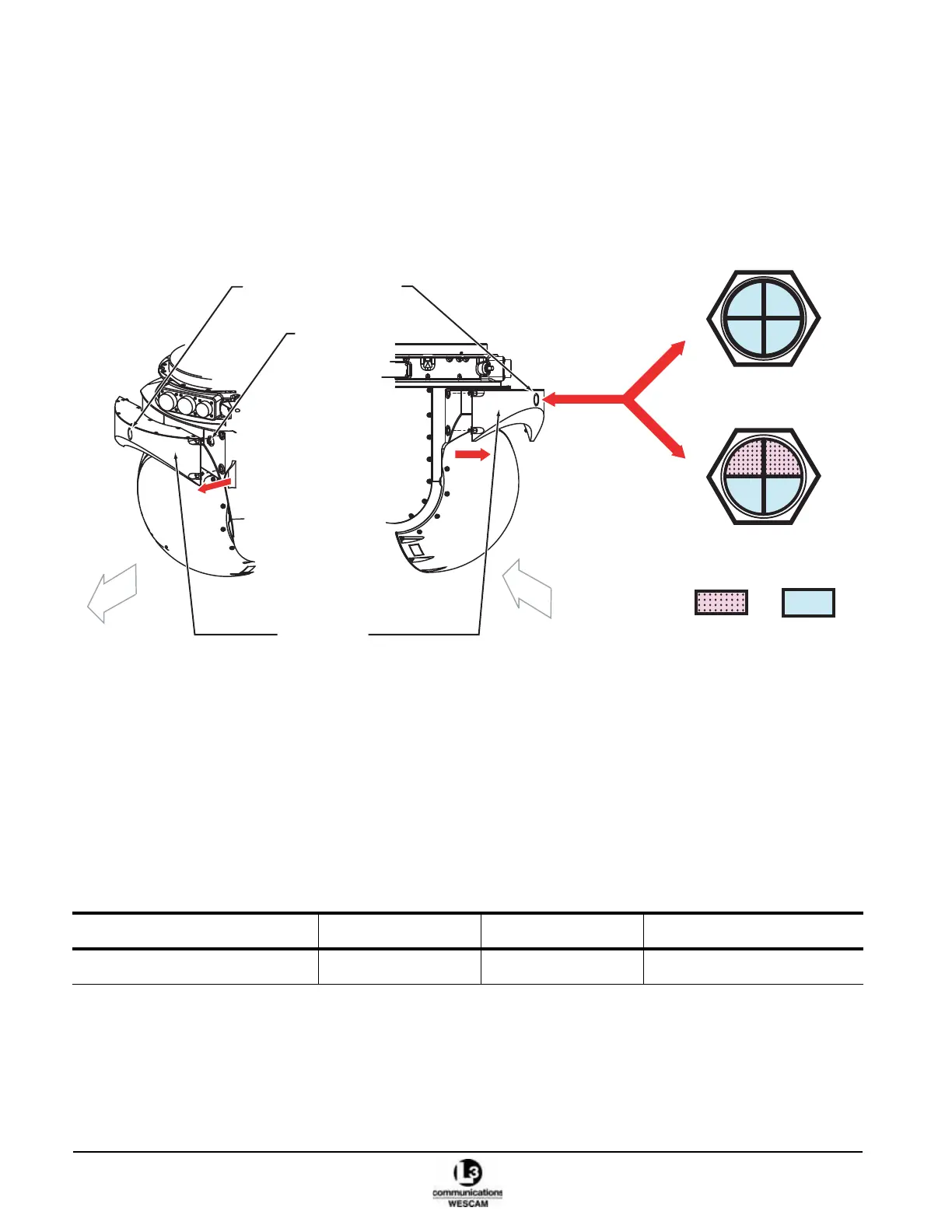
When desiccant material in the desiccant assembly becomes saturated with water it must be replaced. The
humidity indicator on the desiccant assembly will indicate the moisture level. If the upper quadrants labeled 30 & 40
are lavender (pink), the desiccant material must be replaced. There are two options:
• Option 1 – Remove and replace with a new desiccant assembly
• Option 2 – Remove, refill desiccant material and reinstall the desiccant assembly
Figure 6-4 Desiccant Assembly and Humidity Indicator
6.5.1 Remove and Replace the Desiccant Assembly
Removing and replacing the desiccant assembly involves unfastening 4 retention screws. The desiccant assembly
has captive fasteners – held by a spring loaded retention pin rather than a threaded shaft. Like a bayonet style, the
screw requires a 1/4 turn with inward pressure to release. The turret includes a breather check-valve that seals
airflow when the desiccant assembly is removed. Make sure the replacement desiccant assembly is a new unit
sealed in plastic.
Table 6-8 Desiccant Removal — Parts
Description Part Number Quantity Notes
Desiccant assembly 42418 1 pcs
30 40
50
60
All Blue
Quadrants indicating
Operational
30 40
50 60
2 Lavender (Pink) / 2 Blue
Quadrants indicating
Non-Operational
Blue
Lavender
(Pink)
Desiccant
Humidity Indicator
Desiccant
Assembly
Back
Front
Right side Left side
Turret
Breather
Check Valve