5-14 Echo Liquid Handler User Manual
b. Select the wells you want to include in the transfer. For an
explanation on how to select wells in a transfer map, see “
Create a
transfer map” on page 5-14.
c. Click the radio button for Dest 2 and select the wells you want to
include in the transfer. Repeat this process for the remaining
destination plates.
Note: If you are selecting the same group of source wells for all four
destination wells, then click the radio button for All and select the
wells you want to include in the transfer. The software will
automatically create the transfer maps for Dest 1 to Dest 4.
6. Click the F
INISH button after all four transfer maps have been created.
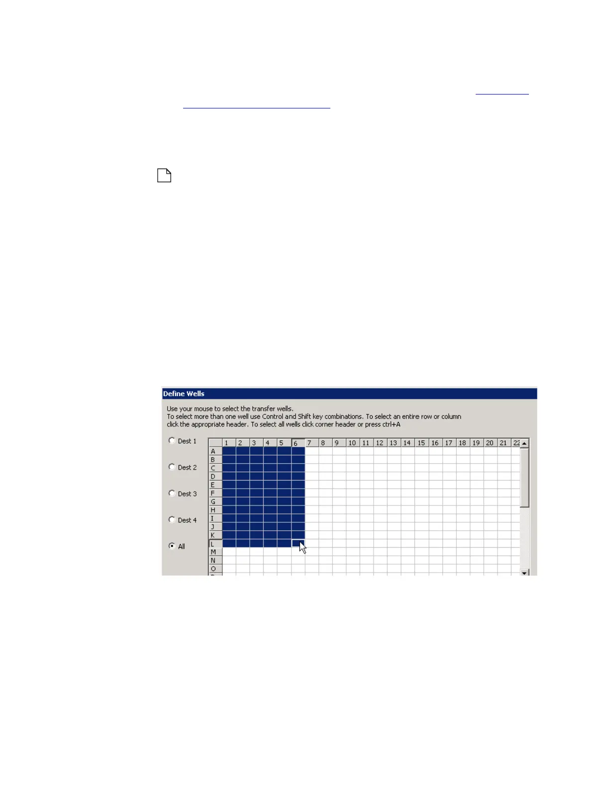
Create a transfer map
A transfer map must be created for each source microplate. The transfer
map defines which source microplate wells contain compound that will be
transferred to the destination plate.
When you click the VIEW/DEFINE button, the DEFINE WELLS dialog box
opens.
Figure 5.19 The Define Wells dialog box
The DEFINE WELLS dialog box shows a simple grid that represents the
microplate. Each source microplate well is represented by a grid square.
The user selects the microplate wells from which fluid will be transferred.
Selected wells (highlighted in blue) will be transferred when the protocol is
run. The dialog box shown above defines a liquid transfer from wells A1