LaCie 12big Rack Storage Server
User Manual page 14
System Overview
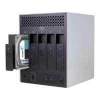
Fig. 13 - Cooling Fan Module
Airflow is from front to rear, with cooling air being drawn across the
drives, through the fans and pressurizing the rear of the enclosure.
The pressurized rear allows the PSU to draw the air that it requires,
and perforations at the rear of the chassis allow cooling airflow over
the processor heatsinks, memory, motherboard and PCI cards.
Back pressure created by rack doors and obstacles is not to exceed
5 pascals (0.5mm water gauge).
The cooling system provides sufficient airflow to make sure that drive
maximum temperatures are not exceeded when the enclosure is at
35°C ambient (sea level) and one fan has failed.
The cooling cage contains ten individual high speed single rotor
axial fans, individually connected to and interfacing with the EM
Card. This interface provides power and speed control to the fans
and returns tachometer output from each fan.
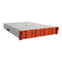
2.10. Drive Carrier Module
The drive darrier module comprises a hard disk mounted in a car-
rier. Each drive bay houses a single low profile 1.0 inch high, 3.5
inch form factor disk drive in its carrier. The carrier has mounting
locations for SAS/SATA drives.
Each disk drive is enclosed in a sheet steel carrier which provides
excellent thermal conduction, radio frequency and electro-magnetic
induction protection and affords the drive physical protection.
The front cap features an ergonomic handle which provides the fol-
lowing functions:
✦ Camming of carrier into and out of drive bays.
✦ Positive ‘spring loading’ of the drive/backplane connector.
Fig. 14 - Drive Carrier Module
2.10.1. Drive Status Indicator
Disk drive status is monitored by green and amber LEDs mounted
on the front of each drive carrier module, under GEM control (see
Fig. 15). Refer to section 4.4.3. Drive Carrier LEDs for a description
of the LED states.
The behavior of these LEDs can be overridden by the customer via
SES.
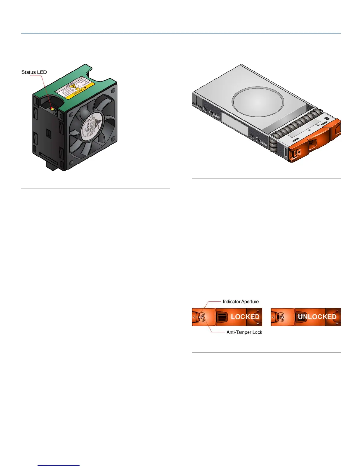
2.10.2. Anti-Tamper Locks
Anti-tamper locks are fitted in the drive carrier handles (Fig. 15)
and are accessed through the small cutout in the latch section of
the handle. These are provided to disable the normal ‘pinch’ latch
action of the carrier handle.
Fig. 15 - Anti-tamper Lock
2.10.3. Mixed Drive Types
SAS and SATA drives may be mixed within an enclosure but drives
of a similar type and rotation speed should be mounted within the
same column of the enclosure.
2.10.4. Dummy Drive Carrier Modules
Dummy drive carrier modules are provided for fitting in all unused
drive bays. They are designed as integral drive module front caps
with handles and must be fitted to all unused drive bays to maintain
a balanced airflow.
 Loading...