LaCie 12big Rack Storage Server
User Manual page 22
Operation
4.4.3. Drive Carrier LEDs
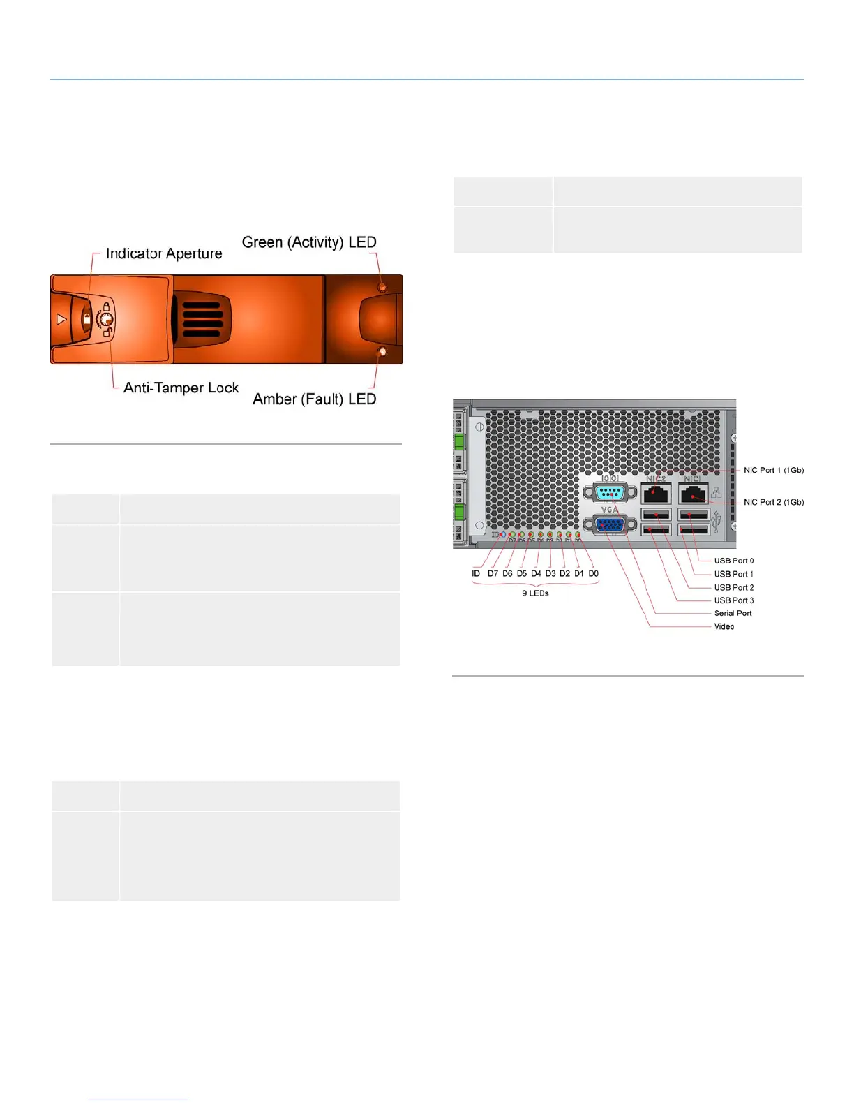
Each drive carrier module incorporates a green and amber LED,
shown in Fig. 24.
Fig. 24 - Drive Carrier LEDs
Table 07 - Disk Drive LEDs
LED Definition
Activity ✦ Flickering green: the drive is powered and has
active I/O.
✦ Constant green: the drive is powered and idle.
Fault
✦ •Off: the drive is functioning correctly.
✦ •Flashing amber: drive identied via SES.
✦ •Constant amber: the drive is faulty.
4.4.4. Cooling Fan LEDs
The cooling fans feature a single amber status LED, as shown in
Fig. 13.
Table 08 - Cooling Fan LEDs
LED Status
Status ✦ Off: the fan is operating correctly.
✦ Flashing amber: this is used to identify the fan
and can be achieved through the firmware.
✦ Constant amber: the fan has a fault.
4.4.5. Rear Panel LED
The rear panel LED (shown in Fig. 23) is used to identify the enclo-
sure in the same way as the ID LED described in section 4.4.1. Ops
Panel LEDs and Switches.
Table 09 - Rear Panel LEDs
LED Status
Enclosure ID Blue: only when activated via the ID LED
switch.
4.4.6. ATX Server LEDs
4.4.6.1. Server Status LEDs
The ATX motherboard I/O panel contains eight LEDs labelled D7
to D0 (from left to right). These LEDs indicate the POST status (see
13.3. POST Code Checkpoints).
Fig. 25 - ATX Server I/O Components


 To Next Page