A: Troubleshooting & Technical Support
XPress™ DR Industrial Device Server User Guide 68
A: Troubleshooting & Technical Support
This chapter discusses how you can diagnose and fix errors quickly without having to contact a
dealer or Lantronix.
LEDs
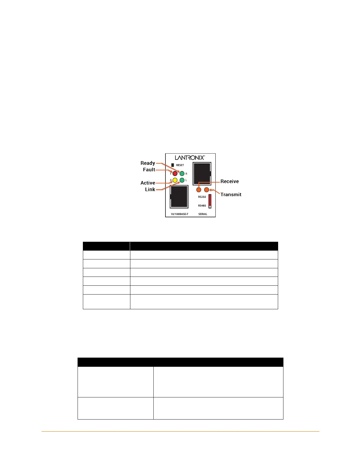
The device contains the following LEDs:
Two Green (R for ready, L for link)
Three Yellow (A for active, serial transmit, and serial receive)
One Red (F for fault)
Figure A-1 Product Information label
Table A-1 XPress DR LED Functions
LED Meaning
R (Green) Ready (Solid=ready, blinking = error message, port busy)
ink (socket connection made) = Solid
A (Yellow) Activity (network) = Random Flashing
TXD (Yellow)
Transmitting serially = Flashes during transmit
Receiving serially = Flashes during receive
F (Red)
Fault in XPress DR communication
(read error) or XPress DR is in Configuration Mode
Simultaneously lit F (Red) and R (Green) LEDs mean something is wrong. If the F (Red) LED is
lit or blinking, count the number of times the R (Green) LED blinks between its pauses. Six
possible blink patterns, detailed in the following table, indicate which fault condition exists.
Table A-2 LED Error Indications
Steady F (Red) and
Blinking R (Green)
1 blink = EPROM checksum error
2 blinks = RAM error
3 blinks = Token Ring error
4 blinks = EEPROM checksum error
Blinking F (Red) and
blinking R (Green)
1 blink = Faulty network connection
2 blinks = No DHCP response
4 blinks = Setup Mode

 Loading...