C: Connections and Pinouts
XPress™ DR Industrial Device Server User Guide 85
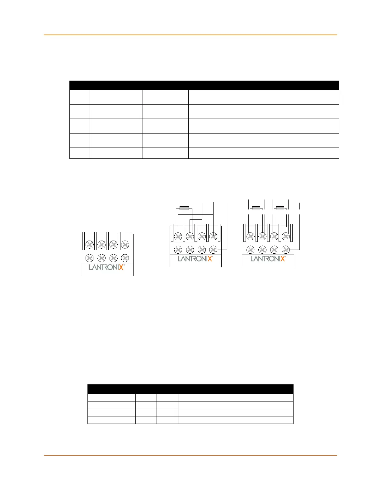
Screw Terminal Serial Connectors
Table C-2 Serial Screw Terminal Pinouts
Pin Direction Name Function
RS-232: RXD (Received Data)
RS-422/485: RX- (Received Data -)
RS-232: TXD (Transmit Data)
RS-422/485: TX- (Transmit Data -)
RS-232: CTS (Clear to Send)
RS-422/485: RX+ (Received Data +)
RS-232: RTS (Request to Send)
RS-422/485: TX+ (Transmit Data +)
Note: You can choose pin 5 or pin 8 as a ground (GND) pin.
Figure C-1 Serial Screw Terminal Pinouts
Note: For RS-485 2-wire functionality, pins 1 & 4 and 2 & 3 of the screw terminals must be
connected together.
Note: Termination resistors (R = 120 Ohm) are used to match impedance of a node to the
impedance of the transmission (TX) line. Termination resistors should be placed only at the
extreme ends of the data line, and no more than two terminations should be placed in any single
segment of a RS-485 network. The terminator resistors may not be needed for your application.
RJ-45 Ethernet Interface
XPress DR supports 10/100Mbit Ethernet through its RJ-45 (10BaseT/100BaseTX) connector.
Table C-3 Ethernet Interface Signals
Signal Name DIR PIN Primary Function
RXD CTS RTS TXD
Rx- Rx+ Tx+ Tx-
GND
1 2 3 4
8
Data+ Data-
GND
1 2 3
4
8
R
R = 120 Ohm, 1/8 W
RxD-
1 2
3 4
8
R
R = 120 Ohm, 1/8 W
RS-485 2-Wire RS-422/485 4-Wire
R
RxD+
TxD-TxD+ GND

 Loading...