C: Connections and Pinouts
XPress™ DR Industrial Device Server User Guide 86
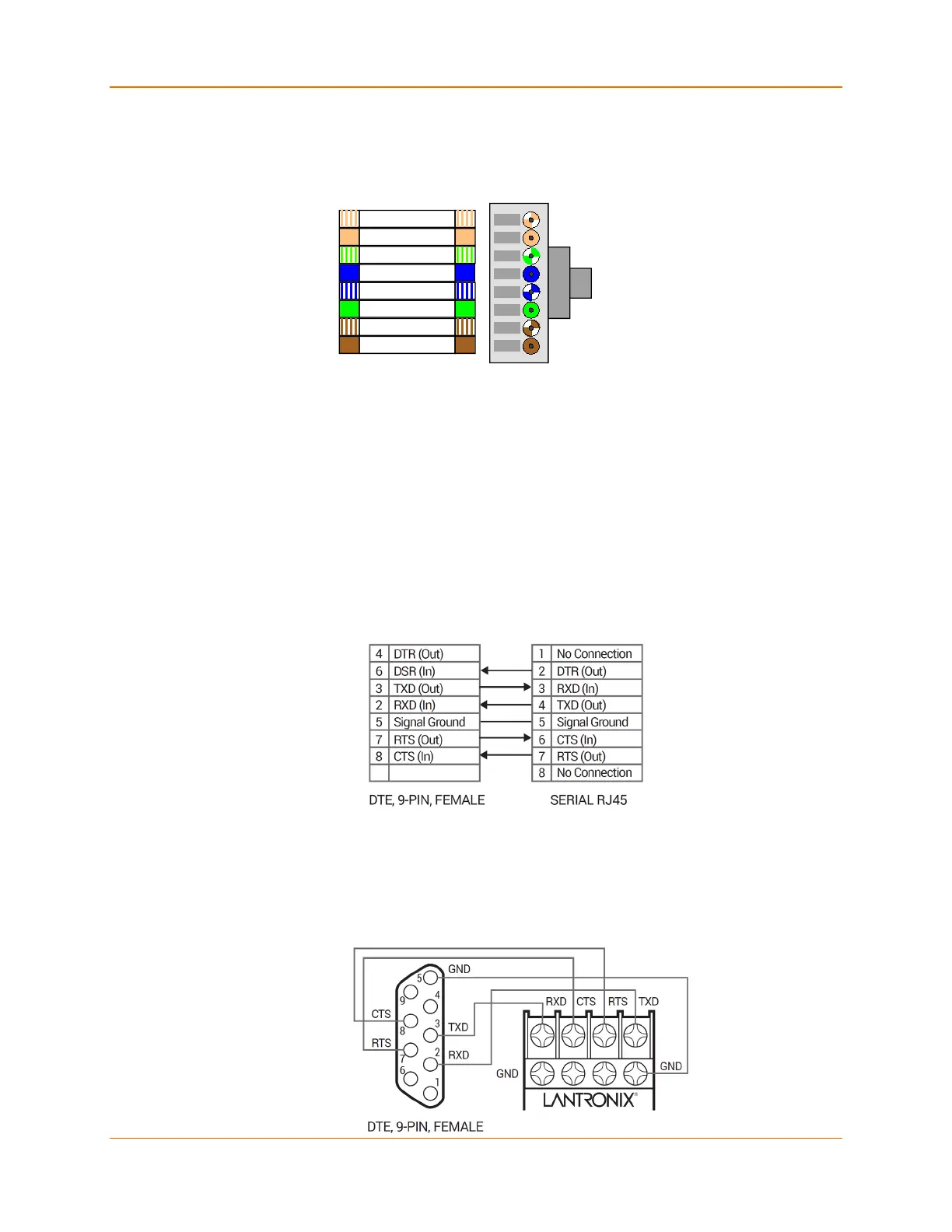
The next drawing shows a typical RJ-45 connector. The color is not standard but very typical of
an Ethernet Patch cable. Pin 1 is located at the top of the connector (Orange + White). The view
is from the end of the connector.
Figure C-2 RJ-45 Connector
Serial Interface Connections
The serial device can be RS-232 or RS-485/422 and the connections can be screw terminals or
RJ-45 connector. This section shows several practical methods for making the hardware
connections. The following diagrams show typical interface cables for the RS-232 Serial interface
and the Ethernet interface.
9-Pin RS-232 to Serial RJ-45
The cable diagram below is for connecting a PC (com port) to the XPress DR serial RJ45 port.
You can use the serial RJ45 port to configure and test port settings prior to connection to your
automation device.
Figure C-3 RS-232 to Serial RJ-45 Connection
9-Pin RS-232 to Serial Screw Terminals
This connection assumes you are connecting a typical PC (COM1) to the XPress DR through the
serial screw terminals.
Figure C-4 RS-232 Configuration
Orange + White
Orange
Green + White
Blue
Blue + White
Green
Brown + White
Brown
View from
Connector End

 Loading...