Sentinel Plus Press Brake Guarding System Operation Manual LS-CS-M-073
Page 19
Original Language Version: 1.04 Released: 19/07/2017
3.9 Special Guarding Modes
There are two special guarding modes which modify the way in which the laser guarding is
configured; Special Tools mode and Thermal Compensation mode.
3.9.1 Special Tools Mode
The tool tip finding process in the Sentinel Plus is designed around V tools that are used in
most press brake operations. Once the tool tip is found the optical protection is set to guard
the danger zone around the tool tip.
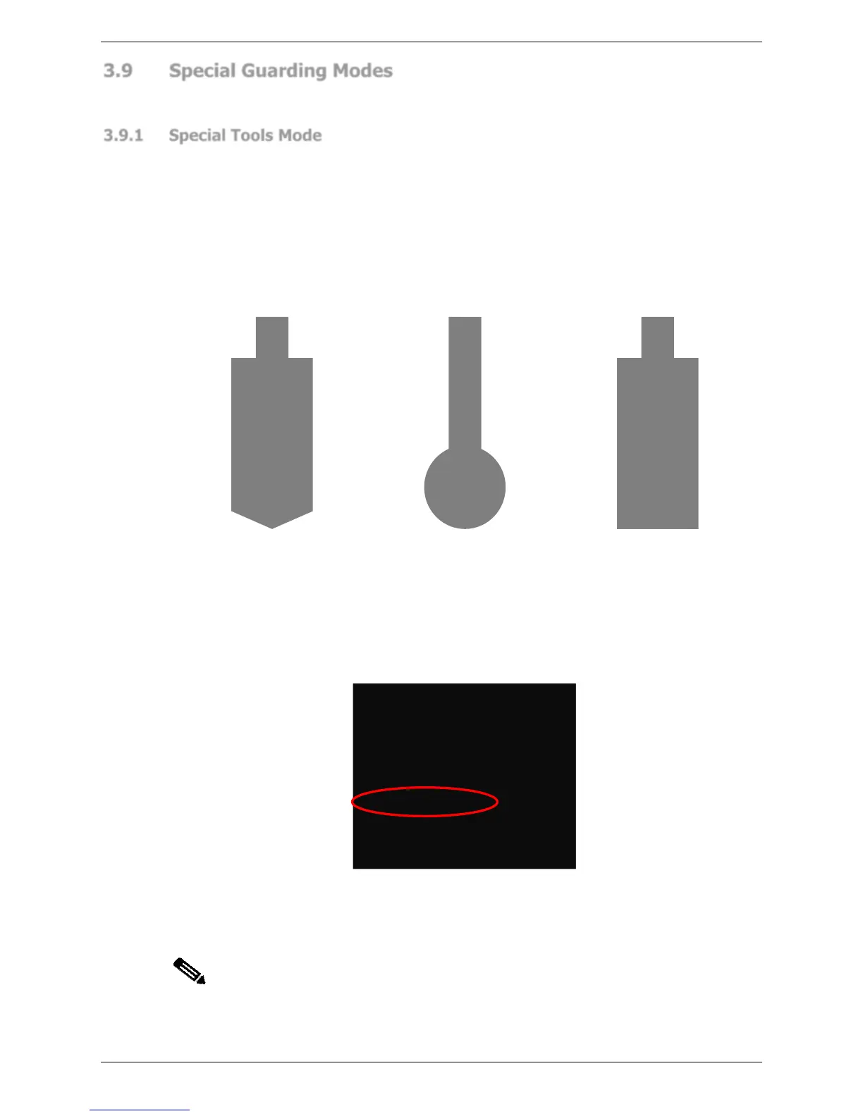
Non-standard tools, such as those shown in Figure 3-7 have silhouettes that place them
outside of the normal tool tip detection range. Large V, large radius or flattening tools
require the use of Special Tools mode, which changes the way in which the Sentinel Plus
detects the lowest point of the tool, and sets the guarded area. This ensures that the
guarded area is appropriate for the non-standard tool, and provides the highest possible
level of protection for the operator.
Figure 3-7: Special Tool Types (left to right) Large V, Large Radius, Flattening
Depending upon the size and shape of the tool the Sentinel Plus may have to increase the
mute point. If the mute point opening is increased by the Sentinel Plus, then the slow speed
point of the press must also be increased appropriately by the machine operator. The
approximate slow speed point (the tool opening in mm) required by the Sentinel Plus is
displayed in the System Information menu, as shown in Figure 3-8 (refer to Section 5.7.1
for more details).
Figure 3-8: Approximate Slow Speed Point
Refer to Table 3-1 (radius tools), Table 3-2 (large V tools), and Table 3-3 (flattening tools)
for the recommended slow speed points.
Note:
In these tables the stated values for each of the tool sizes is nominal only, and
can be detected with a tolerance of +/-3mm during the tool align process. This
may therefore affect the minimum allowable mute or slow speed distance
finally used, but will always be within safe and acceptable limits.