Sentinel Plus Press Brake Guarding System Operation Manual LS-CS-M-073
Page 24
Original Language Version: 1.04 Released: 19/07/2017
4 LZS-005-R Operation
This section describes the operation of the LZS-005-R block laser transmitter and receiver,
and in particular the automatic tool alignment feature of the Sentinel Plus system.
4.1 Alignment Procedure
The LZS-005-R receiver features automatic tool alignment, where the image of the tool
silhouette is analysed by the receiver, the tip of the punch is located and the protection
zone is accurately aligned with the tool tip position. This optimizes the level of safety and
productivity provided by the Sentinel Plus system.
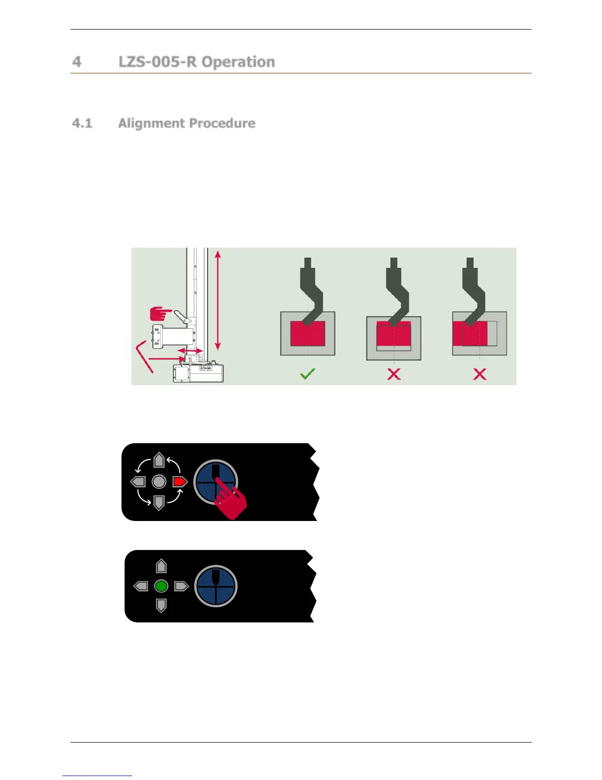
The automatic tool alignment process first requires that the transmitter and receiver are
positioned in accordance with Lazer Safe Block Laser Alignment Guide (LS-CS-M-025
Rev 2.0). This will position the transmitter, receiver and tool within the limits of the
automatic tool alignment process. Figure 4-1 is taken from the alignment guide, and shows
the correct positon for the tool silhouette on the receiver window.
Figure 4-1: Block Laser Receiver Alignment
When the transmitter and receiver have been positioned correctly, the automatic tool
alignment can be performed.
Figure 4-2: Automatic Tool Alignment
Press the Tool Align button on the receiver
and the automatic tool alignment process
will begin.
As the image is analysed by the receiver,
the red LEDs cycle as shown in Figure
4-2. The time taken to locate the tool tip
depends upon several factors – tool size
and shape, the accuracy of the initial
alignment of transmitter, receiver and
punch, environmental conditions etc.
If the automatic tool alignment is
successful the red LEDs stop cycling, and
only the centre green LED lights, as
shown in Figure 4-3.
Figure 4-3: Alignment Successful
If the initial position of the tool silhouette on the receiver is outside the limits of the
automatic tool alignment, the red receiver LEDs indicate to the operator why the alignment
was not successful, and how the position of the receiver must be changed to improve the
alignment.
The LEDs show the direction that the receiver needs to be moved, interpreted as if they are
behind the receiver, looking at the transmitter. Figure 4-4 shows the directions as indicated
by these LEDs.