Sentinel Plus Press Brake Guarding System Operation Manual LS-CS-M-073
Page 25
Original Language Version: 1.04 Released: 19/07/2017
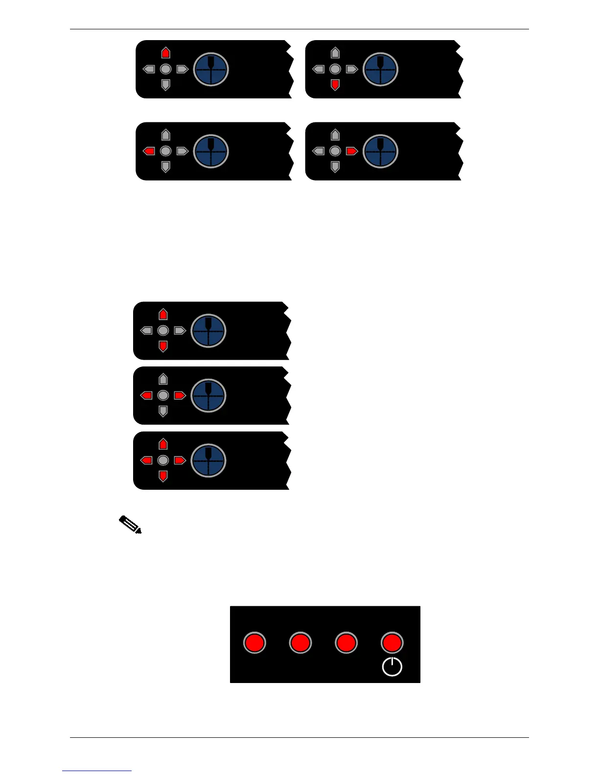
Move the receiver LEFT
(front of machine)
Move the receiver RIGHT
(rear of machine)
Figure 4-4: Receiver Alignment Correction
In some cases (extreme environmental conditions, unusual tool shapes, poor alignment
etc.) the automatic tool alignment may not be able to find the tool tip. Again, the receiver
provides diagnostic information using the red LEDs.
The image captured by the receiver is too dark
to locate any tool silhouette. This may be
caused by an obstruction, or by a poor
alignment.
The image captured by the receiver is too light
to locate any tool silhouette. This may be
caused by a poor alignment, or very high
levels of ambient light shining on the receiver.
The tool tip location has been lost. This may
be caused by the power being cycled on the
receiver, the mute point being reset by the
operator, or the tool silhouette being lost.
Note:
It is the responsibility of the machine operator to ensure that the transmitter and
receiver are correctly aligned. Correct alignment is essential to ensure maximum
protection and productivity for the press brake operator.
LEDs on the side of the receiver indicate when an obstruction occurs to a protected region
(the front, middle or rear) as shown in Figure 4-5.
Figure 4-5: Block Laser Obstruction Indicators