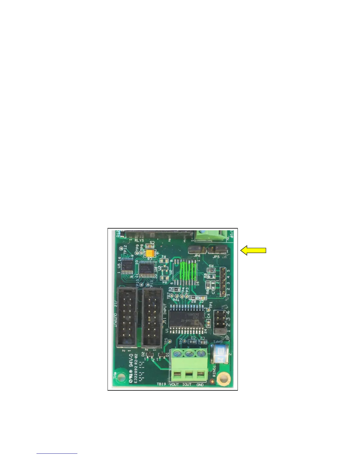
If the SLC-220 unit is equipped with Outputs board/s, pass the 4-20mA cable through the proper
cable gland in the external wall of the enclosure. Then connect the two wires to the contacts of
terminal block TB19 as follows:
TB19 Contact Contact Function
Iout 4-20 mA + (Current source, non-isolated)
GND 4-20 mA - (Current return, non-isolated)
If 0-5 V output is required (instead of 4-20 mA), connect each of the two wires to TB19 as follows:
TB19 Contact Contact Function
Vout 0-5 V + (non-isolated)
GND 0-5 V return (non-isolated)
Note: At this point, the current / voltage output is not galvanically isolated.
Setting the functionality / range of the output is done by jumpers on the Outputs board:
JP5 position JP6 position Range at TB19
2-3 2-3 0-5 V
1-2 2-3 4-20 mA < This is the default setting
2-3 1-2 0-20 mA
1-2 1-2 0-24 mA
 Loading...