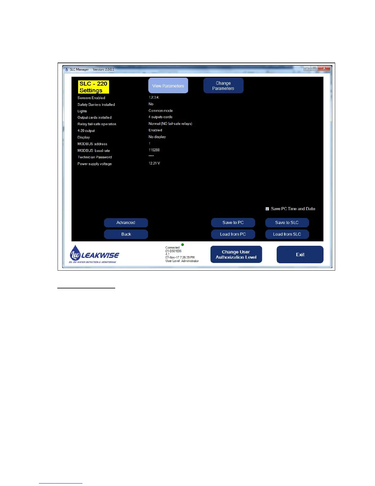
4.5 SLC-220 Settings Screen
This screen enables viewing of general and common parameters.
The parameters are:
1. Sensors Enabled: Shows the enabled sensors. The disabled sensors are not shown. In
the above example, only sensor 1 and sensor 3 are enabled. Only these sensors will be
activated and monitored, and will have influence on all the available outputs.
Note: For disabled sensors, all relays will be de-energized, and all 4-20mA outputs will be
set to 4.33 mA.
2. Safety Barriers Installed: Used for reference only. No actual functionality.
3. Lights: There are two operating modes for the lights: Common or Individual. Refer to
chapter 2.2.6 above.
4. Outputs boards installed: This should represent the actual number of installed Outputs
boards. This can be none, 1, 2, 3 or 4 boards.
The last option is one board with a common function:
Relay #1 will be activated when sensor #1 has Oil status,
Relay #2 will be activated when sensor #2 has Oil status,
Relay #3 will be activated when sensor #3 has Oil status,
Relay #4 will be activated when sensor #4 has Oil status,
Relay #5 will be activated when any of the four sensors has Fail status.
In addition, the Analog output (4-20mA) will be associated to sensor #1.