SLC-220 User Guide Rev 2.0 June 2018
For SLC-220/Basic, the lower board is associated with sensor #1; the upper board (if installed) is
associated with sensor #2.
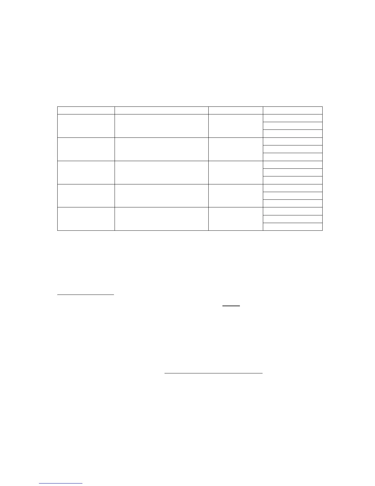
Pass the cable through the proper cable gland in the external wall of the enclosure. Then connect
the wires of this cable to the contacts of terminal blocks TB14 till TB18 of the appropriate Outputs
board as follows:
Water or
Oil / High Oil for sensor #1
Oil or
Oil / High Oil for sensor #2
High Oil or
Oil / High Oil for sensor #3
Air or
Oil / High Oil for sensor #4
Fail or
Common Fail for all sensors
NO: Normally Opened contact,
COM: Common point,
NC: Normally Closed contact.
Arranging the wires:
In SLC-220/Multi, there is one white plastic wire saddle above every Outputs board. Insert the
wires into the saddles and guide them to the left of the enclosure, then down and to the cable
gland.
Each relay has an indicating LED on the board to indicate when it is energized.
The relays can be set to operate in normal mode or in fail-safe mode. Changing the setting is
done in SLC-220 Settings (chapter 4.5).
 Loading...