5
5
4
4
3
3
2
2
1
1
D D
C C
B B
A A
Title
Size Document Number R e v
Date: Sheet of
DWGW SLC 004 2 0
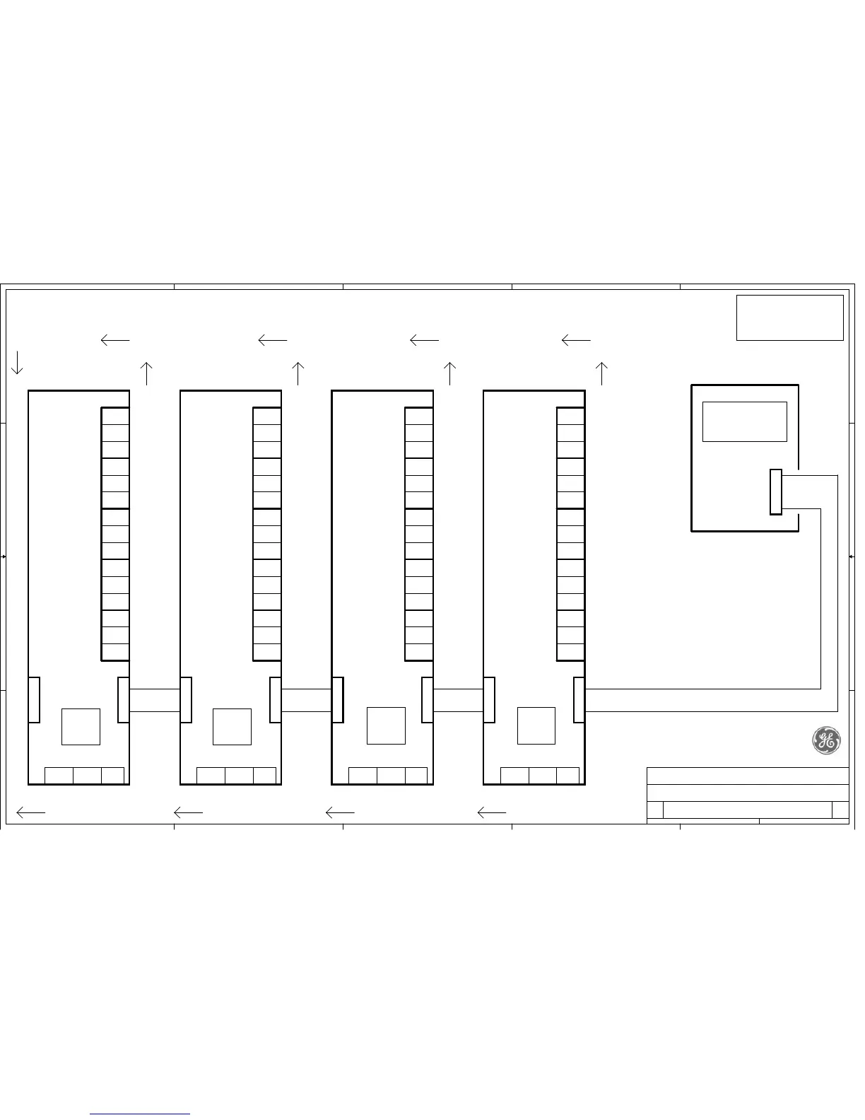
SLC-220 Wiring Diagram - Outputs Boards Connection
B
2 2Sunday, April 12, 2015
GE Analytical Instruments
SLC-220
Main Board
DWG SLC 001 4
J6
OUTPUTS
/14 Flat Cable
NO
COM
NC
NO
COM
NC
NO
COM
NC
NO
COM
NC
NO
COM
NC
TB14
TB15
TB16
TB17
TB18
Relay #1
/ Water
Relay #2
/ Oil
Relay #3
/ High Oil
Relay #4
/ Air
Relay #5
/ Fail
OUTPUTS Board #1
DWG SLC 002 4
J11J12
OUTPUT
INPUT
GNDIoutVout
TB19: Analog Output
1
NO
COM
NC
NO
COM
NC
NO
COM
NC
NO
COM
NC
NO
COM
NC
TB14
TB15
TB16
TB17
TB18
OUTPUTS Board #2
DWG SLC 002 4
J11J12
OUTPUT
INPUT
GNDIoutVout1
NO
COM
NC
NO
COM
NC
NO
COM
NC
NO
COM
NC
NO
COM
NC
TB14
TB15
TB16
TB17
TB18
OUTPUTS Board #3
DWG SLC 002 4
J11J12
OUTPUT
INPUT
GNDIoutVout1
NO
COM
NC
NO
COM
NC
NO
COM
NC
NO
COM
NC
NO
COM
NC
TB14
TB15
TB16
TB17
TB18
OUTPUTS Board #4
DWG SLC 002 4
J11J12
OUTPUT
INPUT
GNDIoutVout1
/14 Flat
Cable
0-5V 4-20mA GND0-5V 4-20mA GND0-5V 4-20mA GND0-5V 4-20mA GND
TB19: Analog OutputTB19: Analog OutputTB19: Analog Output
Relays Contacts Wiring
Analog Outputs Wiring
NO: Normally Opened
NC: Normally Closed
COM: Common Point
Relays Contacts:
24 VDC is Supplied to Outputs Boards
from Main Board thru the Flat Cable
/14 Flat
Cable
/14 Flat
Cable
/14 Flat
Cable
JP4: OFF
JP3: OFF
JP2: OFF
JP1: 0N
JP4: ON
JP3: OFF
JP2: OFF
JP1: 0FF
JP4: OFF
JP3: OFF
JP2: ON
JP1: 0FF
JP4: OFF
JP3: ON
JP2: OFF
JP1: 0FF
 Loading...