OPERATOR’S MANUAL
The following examples illustrate how you might use the instrument's enhanced resolution function.
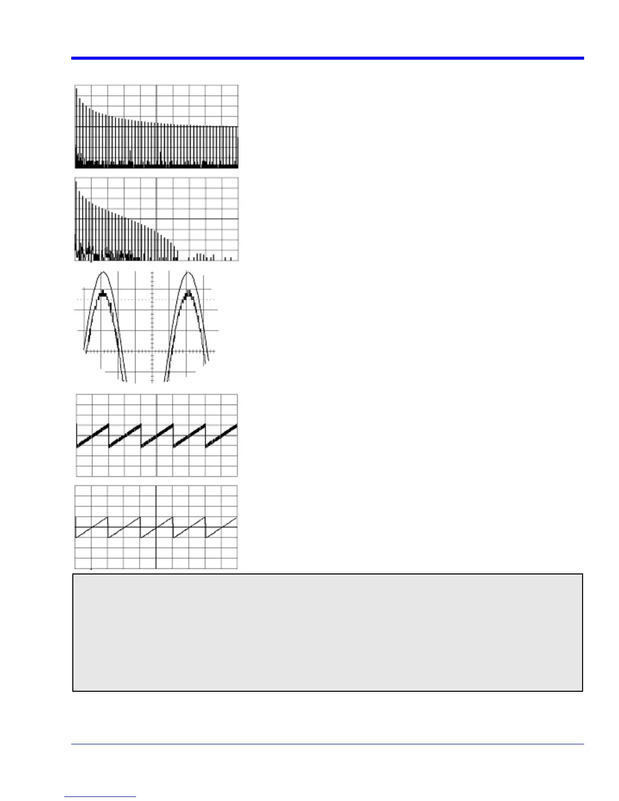
In low-pass filtering: The spectrum of a square signal before (left top) and
nal.
cement, the lower the resulting bandwidth.
after (left bottom) enhanced resolution processing. The result clearly
illustrates how the filter rejects high-frequency components from the sig
The higher the bit enhan
To increase vertical resolution: In the example at left, the lower ("inner")
enhanced resolution
trace has been significantly enhanced by a three-bit
function.
To reduce noise: The example at left shows enhanced resolution of a
noisy signal. The original trace (left top) has been processed by a 2-bit
enhanced resolution filter. The result (left bottom) shows a "smooth" trace,
where most of the noise has been eliminated.
Note: En ution can only improve t ace; it cannot improve thanced resol he resolution of a tr he accuracy or
linearity uantization. The pass-b al attenuation for signal -off of the original q and will cause sign s near the cut
frequency. Th st frequencies passed may be sli attenuated. Perform the filtering on finite record e highe ghtly
lengths. Data e lost at the start and end of the wa rm: the trace will be slightly shorter after filtering. will b vefo
The number of samples lost is exactly equal to the le the impulse response of the filter used: between 2 ngth of
and 117 sam Normally this loss (just 0.2 % of a point trace) is not noticed. However, you might ples. 50,000
filter a record re would be no data output. In r, the instrument would not allow you so short the that case, howeve
to use the ERES feature.
WRXi-OM-E Rev C 133

 Loading...
