5-24 Performance Verification Rev. D Sept 2007
Recall Bandwidth - CH1 10mv.lss or configure the DSO:
Panel Setups : Recall FROM DEFAULT SETUP
Channels Trace ON Channel 1
Input Coupling : DC 50Ω on all 4 Channels
Input gain : 10 mV/div on all 4 Channels
Input offset : 0 mV on all 4 Channels
Trigger setup : Edge
Trigger on : Line
Mode : Auto
Time base : 50 ηsec/div.
Change parameters
P1 : PK-PK of C1
P2 : Freq of C1
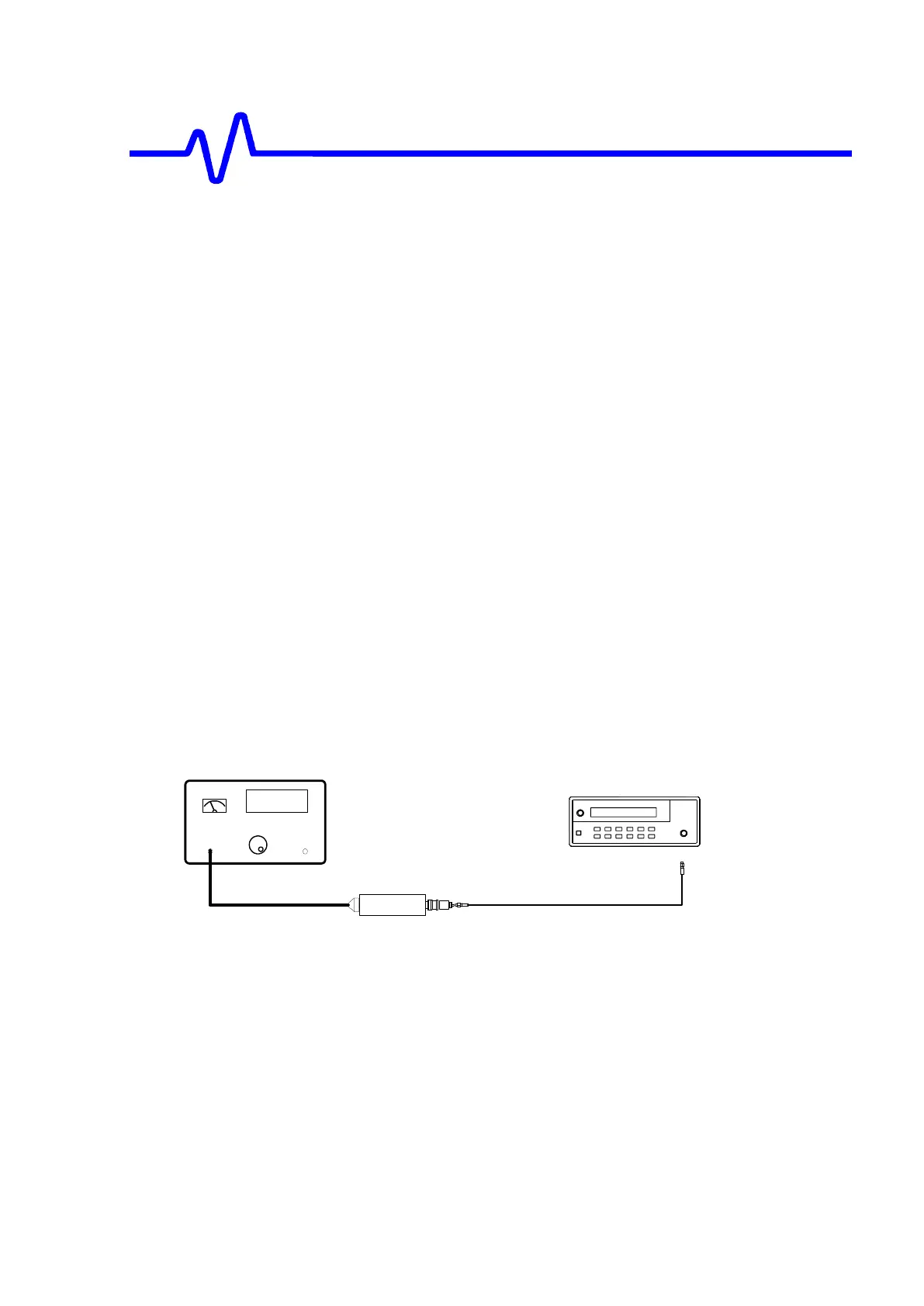
Connect the HP8482A power sensor to the power meter.
Zero and calibrate the HP8482A power sensor using the power meter Power
Ref output.
Connect a BNC adapter to the HP8482A power sensor.
Connect a 50Ω SMA cable to the RF output of the HP8648B
generator and then through the necessary adapters to the power sensor. It is
very important that the same cable/generator be used throughout this BW
procedure and that the SMA connectors are torqued at all their mating locations.
Power Sensor
Power Meter
Power Ref
Output
Sensor Input
Sine Wave
Generator
Figure 5-3 : Power Meter Equipment Setup
Set the generator frequency to 10 MHz
Set the generator amplitude to measure 8 µW on the power meter.
Read the displayed generator output amplitude, and record it in the third
column of Table 9.
 Loading...


