Numbers Components
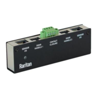
Dip switches for conguring the Normal state of each CC channel. See
Adjusng DIP Switches (on page 53).
• Top row:•
Dip switch 1 controls CC2.
Dip switch 2 controls CC3.
Dip switch 3 controls CC4.
Dip switch 4 controls CC5.
• Boom row:•
Dip switch 1 controls CC1.
Dip switch 2 controls the built in hall effect sensor.
Tip: If an alert is shown for this hall eect sensor, you can disable it
by turning on/o DIP switch 2.
 Loading...